4G63 to Starion Wiring How-To
This section may make the process of wiring the car less of a burden. It is quite simple as long as you label wires before you cut them from plugs.
Using this guide, you can keep many of the factory options on the car like air conditioning and evaporative emissions. This guide will also alow you to keep all factory gauges. It is possible to keep cruise control, but I do not have that info at this time. Several features are integrated into the DSM engine harness which are not needed becuase they are already integrated into the Starion chassis wiring. These include: defogger, windshield wipers, brake fluid level, and the transmission reverse switch.
What You Will Need
- 4G63 Engine Wiring Harness
- Starion B38 Female Plug or Equivalent
- solder
- soldering iron or mini butane torch
- shrink tubing
- masking tape
- fine tipped Permanent Marker (Sharpie)
- pocket knife
- Any other little tools you want
Getting Started
If you are afraid of all these wires and computers, the best thing to do is to isolate and separate different parts of the bundle.

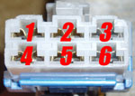
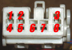
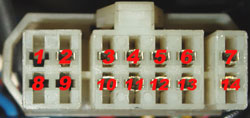
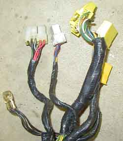
The other half of the harness resides inside the passenger compartment (they're usually alot cleaner). You'll see the three yellow plugs for the ECU, a white plug for the main relay, a white plug with 6 pins, another white plug and a blue plug. Don't panic if your harness has more or less plugs or plugs with different numbers of pins. Mitsubishi changed things around a little between years and models, but the basics are all still the same. If at any point you find a plug that is different than what is listed below, use an ohm meter to determine where it goes. Using the harness layout, you should be able to determine its function.
 and
and
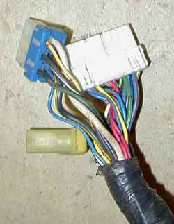
To the left we have the ECUplugs (3 yellow plugs), the main relay plug and C-67. Connectors C-57,C-58, and C-59 are shown on the other photo. C-57 is the small white/yellow one with only one BIG wire. C-58 is the white plug and C-59 is the white/blue plug.
|
|
|
|
|
|
Label Everything
Don't skip this step. Who knows if half way though it you will have to walk away for a week. Using the pin-outs from above, find each wire that you will need to keep. I have bolded these for easy reference.
B38 - The Starion Half of Wiring
Luckily, the engineers of the Starion wiring kept things tidy. Only one plug connects the chassis to the engine (basically). This plug is called "B-38". Knowing B-38 is all you need to know if you're going stand alone. How about that?
|
|
|
|
Here is some more info that you might find helpful
Pin 2: 12V power for backup memory in the ECU. This fuse (10A) is in the fancy fuse box below the steering wheel.Pin 3: This wire is cruise control related. I am not sure of the actual function.
Pin 5: 12V power for when the ECU is on. On the DSM this fusible link was located on the positive battery terminal. On the Starion this is the "ECI" fusible link wire (bullshit).
Pin 6: The inhibitor switch is what keeps a car with an automatic from starting when it is in gear (that could get ugly). Actually it could be ugly in a manual too. That is why cars usually have a clutch switch... and surprisingly the Starion has no such safety device. You don't even need to push the clutch to start this thing. Anyways... This should be grounded on a manual transmission car.
Pin 7: Oil Pressure Gauge. This works too! Oil pressure gauges rule!
Pin 10: Hooking up to this will allow you to check ECU codes with the Starion checker plug located above the glove box. It would be better to upgrade to an OBDI plug.
Pin 12: Temp Sender signal to cluster. Temp sensor works!
Pin 13: ECU boost level. Stock boost gauge works!
Pin 14: There is not a VSS in the transmission. The signal is generated by the cable turning the reed switch in the speedometer. This generates the signal and sends it to the ECU. I don't really know what a 1G ECU would do with a Vehicle Speed signal.
Fuel Pump - The fuel pump comes from the ECI control relay. This wire is rather thick. You will need to find a plug to connect this to the chassis harness' fuel pump wire. I usually cut a new 1-pin plug off a parts car and solder it in.
The Tachometer - The tach gauge signal comes off of the coil on the Starion. It runs up the driver side fender and into the dash. The DSM tach signal comes from the coil pack and through the ECU. Its your call to tap in at the coil or at the ECU.
Oil Pressure Gauge - You will need to run several wires from the oil filter housing. One of these is for the oil pressure gauge. Simply tie this wire into pin 7 of B-38 to have a functional oil pressure gauge.
Label B-38 Wires
Label all of the wires on your donor B-38 plug. The bolded items on the above list are the wires you will need to label. If you are using a similar plug cut from another part of the chassis harness, be sure to switch around the wires so that you have appropriate guage wires where you need them. Examine your chassis male B-38 and try to match wire sizes.
Cut and bundle
Once you have all the wires labeled, you can now start removing the plugs. Cut them off paying attention to wire lengths and such. Now dig through the labels and find all of the wires that you will need for the B-38 plug. Bundle these together. You may also want to bundle together the wires for the different test plugs, dash wires and even the wires for the OBDI plug you might decide to add. There are several wires that are needed, but do not run through the B-38 plug. These include:
- Tachometer
- Check Engine Light (CEL)
- Oil Pressure Light
- Fuel Pump Wire
- OBDI - Data Transfer
- OBDI - Self Diagnosis
Connecting B38 (Female) to The DSM Harness
The next step is to connect the B38 (Female) plug to the DSM Harness. Take your labeled B-38 plug and lay it next to your B-38 bundle of wires coming off the engine harness. Not forgetting you slip on your shrink wrap, twist each corresponding wire together and solder.
Not quite done yet. You still need to run a few more wires to the dash. The tachometer wire will need to tie into the dash at the B-22 plug located on the driver's side of the gauge cluster. The other two things to run are warning lights. You may need to wire in your own light bulbs and find a way to mount them. It is also possible to trace out any unused warning lights in the stock cluster. It would be good practice to place a plug for these 3 wires so that the engine harness can be easily removed without needing to pull wires behind the cluster.
Now you should have a DSM harness which you can plug into your Starion!
RWD Issues
Because the orientation of the engine has changed, some parts of the EFI system have moved around. Now you will find that some of the plugs do not reach. The most obvious spot for this comes from moving the throttle body to the opposite end of the intake. You will need to extend several plugs for this:
- Throttle Position sensor (TPS)
- Idle Control Solenoid (ICS)
- Close Throttle Switch
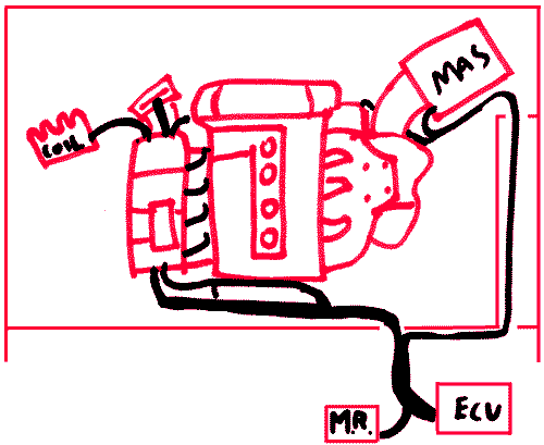
The Mass Air Sensor (MAS) wires may need to be extended as well depending on where you will be routing them. It is tight, but if you route the wires like below, you MAS segment is just long enough.
Removing Unused Plugs
Some people like to remove any unused plugs from the harness. Since you will probably be unlooming a majority of the harness to move plugs around you might as well remove some un-needed wires and plugs. The only downside to this is that you will be unlooming 90% of the harness.
Test, Loom, Install
You have no doubt learned some new things doing your own wiring harness. Use what you have learned to test your harness before you plug in your ECU. Using an ohm meter and your brain, check to see if the sensors actually send their signal to the plug and pin that they are supposed to. Pin out diagrams are available on this site to help with this process.
When you are comfortable that your harness is correctly converted, loom it up. Looming will help to protect your wires from rubbing and snagging. Electrical tape tends to be a real mess once it gets oily. Instead use masking tape to hold things together. It comes appart easily but is strong enough to hold everything together. You will need to cover it though. I prefer to used convoluted tubing for this with zip ties every few inches to hold it together.
Now you can install your harness. Be sure to check for slack in critical areas. Also, make sure the harness does not run to close to hot exhaust manifolds or pipes.
© 2012 Cybernetics


