Autronic
Throughout the process of wiring my car for the Autronic engine management, I kept track of exactly how I wired each component together. This page describes, with diagrams, how I connected each part of my engine management system together. I hope this page helps to pool as much info on using an Autronic SMC on a 4G63. I also hope that it will help people to use the various components in similar setups.
There are serveral parts of the wiring that are just to elementary to include here. I used the Autronic Air Intake Temp Sensor which is wired per the Autronic wiring diagram. The Water Temp Sensor is impossible to mess up as well.
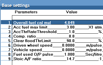
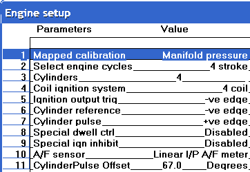
Below are two of the screens that you use to setup the engine configuration. This setup is for a 2.4L 4G64 with a 2.0L head. The compression ratio is 8.8:1 which will probably be close to what others with the 2.4L 6 bolts are running. I am using an Autronic CDI with Denso Coil on Plug. I am using the stock Starion cluster and tach getting its signal from an Autronic Tach Adapter. The firing order for the 4G63, like most inline 4 cylinder engines, is 1-3-4-2. This is not configured in software, but rather in which output is used to trigger each coil. The engine is also using an Innovate LC-1 Wideband (Settings shown are for the Autronic Analyzer).
TPS Wiring
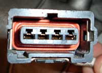
91-94 DSM TPS, there are 4 wires, only 3 of these are needed for the Autronic. This applies to both turbo and non-turbo throttle bodies.
| TPS Pin | Name | SMC Pin |
| 1 | +5V Sensor Power | 19 |
| 2 | Throttle Position I/P | 18 |
| 3 | Not Needed | X |
| 4 | Sensor Ground | 17 |
You may also want to use a Ford Throttle body. I wired one up so I'll post that information as well.

| TPS Pin | Name | SMC Pin |
| A | Sensor Ground | 17 |
| B | Throttle Position I/P | 18 |
| C | +5V Sensor Power | 19 |
CAS Wiring
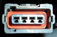
One of the features of the Autronic was that it supported the Mitsubishi CAS trigger wheel. This freed me from having to mount a trigger wheel to my crank pully and from making a bracket for a sensor. All I needed to do was wire up the 4 wire CAS plug to the 4 wires of the ECU. If you wire it up and are still getting sync errors, you may have put the CAS in 180 degrees off.
| CAS Pin | Autronic Label | SMC Pin |
| 1 | Reference Trigger I/P | 8 |
| 2 | Cylinder Pulse Trigger I/P | 32 |
| 3 | Trigger Supply | 20 |
| 4 | Trigger Ground | 31 |
Configuring the Autronic Software for the DSM CAS is pretty straight forward. There are some settings that need to be set though. The screens at the top show how my engine was setup. I'll point out what settings are specific to the DSM CAS.
On the Engine Setup Screen:
- Set the Cylinder Reference to -VE
- Set the Cylinder Pulse to +VE
- Set the Cylinder Pulse Offset to 67 degrees
Ignition System - MSD DIS-4
To wire the SMC to the MSD DIS-4 CDI use this diagram. It already takes into account the 1-3-4-2 4G63 firing order. (This is the same firing order for most 4 cylinder engines otherwise you'd have a very odd looking crank.) This wiring for the DIS-4 was actually posted on the Autronic website. You will need to set the Ignition Output Trigger type on the Engine Setup screen to +VE for the MSD Ignition.
I set the dip switches for the following settings:

Ignition System - Autronic CDI
To wire the SMC to the CDI to the coil on plug setup you need to use this wiring diagram. Set the Ignition Output Trigger type on the Engine Setups screen to -VE for the Autronic CDI. The other pins on the CDI are listed in this Pinout.
Note that the Autronic CDI triggers the positive side of the coil (-VE) while the MSD triggers the negative side of the coil (+VE). If you set this wrong in the software the car may run, but it'll hardly run at all. Just be sure that you've selected the correct Ignition Output Trigger type on the Engine Setup. It is possible to switch an already made harness from -VE to +VE. You'll need to switch the pins in the coil plugs and hook the corresponding coils up to the proper outputs as per the diagram.
Autronic Tach Adapter
I had my Autronic dealer look at the gauge cluster wiring diagram. He determined that since the stock tach was triggered by the negative side of the coil, and that the Autronic CDI has a +12V square wave output, I would need a tach adapter. The wiring was pretty easy to follow. It was so easy, he wrote the directions on a post it note, but you can find the directions on the Autronic site as well. Basically, you tie 1 yellow wire to each of your ECU outputs (CDI inputs). Since I am using 4 channels I hooked up all 4 yellow wires. Additionally, red goes to switched +12V, black goes to ground, and white goes to the tach.
Denso Coil On Plug
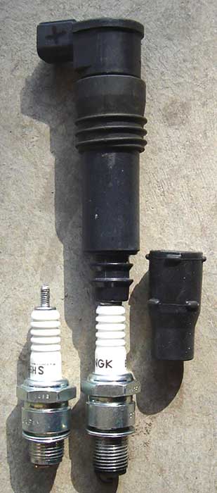
The Coil on Plug setup is very clean. No Spark Plug Wires. Only a small harness containing 6 wires leading from the CDI to the valve cover. The coils do not require a retainer plate either. Using NGK BP#ES plugs with the unscrewable end, you can just clip the coil right onto the plug (as the name implies). They do sit a little to high to cover with a flat plate, but the stock cover may work. The GSXR coils are designed to be used with a CDI system from the factory.
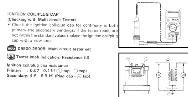
This image was taken from the '96-'00 GSXR-600 Factory Service Manual and gives info on the testing procedures for the coils. It also shows the polarity of the coils which becomes critical when wiring up either a +VE or -VE harness.
Innovate LC-1 Wideband
Autronic says that the Innovate sensors do not output the proper signal. Perhaps the signal isn't as perfect as their sensor's output, but it seems to be fine for datalogging and rough tuning if not fine tuning. The Autronic SMC and SM2 require a 0-1v 02 input with 0V @ 10 AFR and 1v @ 30 AFR so this will focus on that range (sorry SM4 users).
Wiring is pretty straight forward. Note that the LC-1 is different from the LM-1 and therefore does not need any additional circuitry to work properly. The 12V power (red)wire needs to go to an ignition (switched) power source. Its best to connect it to the same ignition signal as your SMC so that you don't harm the sensor by running the engine without it being powered. The Heater Ground (blue) gets grounded to any good ground. The You need to connect the Analog Out (green) and System Ground (white) to the SMC's sensor ground on Pin 17. Either the Analog Out 1 (yellow) or Analog Out 2 (brown) need to go to the SMC's O2 input which is Pin 7. The final wire is the Calibration (black) wire. This goes to a switch and an LED and lets you perform a free air calibration when the conditions are right.
There are 2 ways to program the output of the LC-1 so that the Autronic understands:
- Program the LC-1 to output 0V @ 10 AFR and 0.5V @ 20 AFR.
- Program the LC-1 to output 0V @ 10 AFR and 5V @ 20 AFR and put a 10:1 voltage divider on the LC-1 output

If you'd like to make sure that the sensor output is being read correctly you can program the analog outputs temporarily to output a flat line voltage by entering the same voltage in both fields for the two analog out programming points. This way the analog output voltage will be fixed, independent of the current AFR and can therefore be compared to the readings in the Autronic virtual dash. If you have the luxury of having two computers next to each other, you can compare the LC-1 AFR to the Autronic AFR to get an idea of how close of a match they are.
© 2012 Cybernetics
