connector and some wiring

All the beeping, zapping bits

Moderators: DJpowerHaus, mattmartindrift

Post Reply
mr.andaya
Addict
Posts: 76
Joined: Fri Oct 24, 2008 1:40 pm

connector and some wiring

Post by mr.andaya »

hey guys,
im working on the harness for my quest and i ran into a few snags.

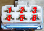
first one is what does this go to
Image
i see on the site it says tach signal cleaner(right by the knock sersor), but does any one have a pic of this?

i also have a few wire questions, i have a few wires i dont know where they go.
1. C-59 pin 5 + feed for the cas and coil packs
2. C-59 pin 6 + fuel pump
3. C-58 pin 3 Ignition Pulse Detect (ECU pin 109)

is C-57 needed?

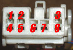
this is where i got this info from, i changed the numbers to the 86 numbers. its kinda confusing

Pin 3: 12V power for backup memory in the ECU. This fuse (10A) is in the fancy fuse box below the steering wheel. constant 12v?

Pin 2: 12V power for when the ECU is on. On the DSM this fusible link was located on the positive battery terminal. On the Starion this is the "ECI" fusible link wire (bullshit).switched? kinda doesnt make sense fuse block on dsm battery is constant right?

Pin 5: Oil Pressure Gauge. This works too! Oil pressure gauges rule!i need to run only one wire to the oil pressure switch correct?

Pin 6: Hooking up to this will allow you to check ECU codes with the Starion checker plug located above the glove box. It would be better to upgrade to an OBDI plug.

Pin 8: Temp Sender signal to cluster. Temp sensor works!

Pin 9: ECU boost level. Stock boost gauge works!

Pin 10: There is not a VSS in the transmission. The signal is generated by the cable turning the reed switch in the speedometer. This generates the signal and sends it to the ECU. I don't really know what a 1G ECU would do with a Vehicle Speed signal.

Fuel Pump - The fuel pump comes from the ECI control relay. This wire is rather thick. You will need to find a plug to connect this to the chassis harness' fuel pump wire. I usually cut a new 1-pin plug off a parts car and solder it in. pin 2 on the dsm relay?

The Tachometer - The tach gauge signal comes off of the coil on the Starion. It runs up the driver side fender and into the dash. The DSM tach signal comes from the coil pack and through the ECU. Its your call to tap in at the coil or at the ECU. do i need to 90 tach adapter?

Oil Pressure Gauge - You will need to run several wires from the oil filter housing. One of these is for the oil pressure gauge. Simply tie this wire into pin 7 of B-38 to have a functional oil pressure gauge.if 1 is for the sending unit what are the other wires for?


im sorry if this doesnt make any sense.

thanks guys
-joe
mr.andaya
Addict
Posts: 76
Joined: Fri Oct 24, 2008 1:40 pm

Post by mr.andaya »

ima start going through the wiring schematics
MightyMike
Knowlege Seeker
Posts: 19
Joined: Fri Aug 14, 2009 2:39 am
Location: Sarasota, Florida

Post by MightyMike »

that connector you show yes goes to a "tach" cleaner, which is a small little box that was normally bolted to the brace from intake to block, this was a 1990 only thing.

trying to trace the C-59 pins....
1 - power feed for CAS, Coil, most all sensors comes from a power wire from the main power relay
2 - fuel pump signal supposed to come again from a green wire from main relay... this screwed up on mine, worked, but turned off when cranking... so i just key on'ed my fuel pump
3 - ECU Pin 109 would be like... use for dash tach if you have one, or aftermarket tach.

C-57 not sure, cant seem to find it on my diagrams in the 2.0L turbo MPI circuit anyways so probably not.

the pin numbers your talking about past this im not sure what your refering to.


pin 103 on ecu is 12v constant for batter backup, yes 10a fuse.
(found my pic, if you have the same adobe crap the 1 is missing, but look closer at the connector, c-64 look at the numbers so yeah 103)

key power pin 110

oil pressure question, yes just the one wire, its just a pressure ground.

fuel pump wire, yes pin 2, should be BG

yes need the tach cleaner, its in line.
take dash tach from pin ECU pin 109, the other tach at pin 21 is ECU signal only. and for SAFCs.


Hope some of this helps
1995 Lancer GSR (RHD Hotness)
1989 Mighty Max (Project)
1992 Dodge Stealth RT/TT
boise-nic
Addict
Posts: 220
Joined: Mon Feb 09, 2009 8:15 pm

Post by boise-nic »

About the fuel pump...The thick black/green wire from the MPI relay box powers the fuel pump. I thought there were two power circuts for the pump. One circut to prime it when the key is on/starting and the other circut tales over while it's running. If there is two, do they both feed from the black/green wire off the MPI? I think I may just solder the black/green wire to the fuel pump wire with an inline fuse to see what happens. Also, where is the fuel pump grounded at? Back at the ground for the MPI?
boise-nic
Addict
Posts: 220
Joined: Mon Feb 09, 2009 8:15 pm

Post by boise-nic »

boise-nic wrote:About the fuel pump...The thick black/green wire from the MPI relay box powers the fuel pump. I thought there were two power circuts for the pump. One circut to prime it when the key is on/starting and the other circut tales over while it's running. If there is two, do they both feed from the black/green wire off the MPI? I think I may just solder the black/green wire to the fuel pump wire with an inline fuse to see what happens. Also, where is the fuel pump grounded at? Back at the ground for the MPI?
Looking at the wiring diagrams, pin 2 (BG) of the MPI connects directly to the fuel pump and pin 13 of the ecu. Just have to locate where the ground wire is at.
mr.andaya
Addict
Posts: 76
Joined: Fri Oct 24, 2008 1:40 pm

Post by mr.andaya »

im tring to make a plug n play harness for my 86 starion.

im looking over schemitcs right now.

-joe
mr.andaya
Addict
Posts: 76
Joined: Fri Oct 24, 2008 1:40 pm

Post by mr.andaya »

ok i found a few mistakes on the site with the c-59 plug, this is what threw me off.

c59(blue/white plug) is
Image


1-defogger
2-starter feed(black/yellow(pin 7 on 86 b-38(black/yellow))
3-defogger relay
4-+ fuel pump(black/green(90 schem says black/white but my 90 harness is black/green))
5-+ feed for coil packs(black/white(12v switched(pin 2 on 86 b-38(blue))
6- VSS(yellow/white(pin 10 on 86 b-38(yellow/white))

small white plug with 8 pins..
Image

pin1(red /black(ecu 103)) and main relay C-67 pin6(black/red(old dsm fuseable on batt)) go to constant power(86 quest b-38 pin 3(black/red?)

and last but not least,i want to switch to a newer power transistor this is what i think will work.

move white(fuel pump control 109) wire to power transistor
tap black/white(mpi control relay 110) wire to power transistor

that would get rid of the noise filter and have power to the coils and power transistor.

other than wiring up the alt it should be a runner.
i hope this info helps people and ill pm dj to see it he can change some on the wiring page.

-joe
Post Reply