Page 2 of 2
Posted: Sun May 01, 2011 4:26 pm
by JDOliver
Looking good, thanks for the update.
Posted: Wed May 04, 2011 6:11 pm
by jeffball610
Posted: Sun Nov 20, 2011 5:47 pm
by jeffball610
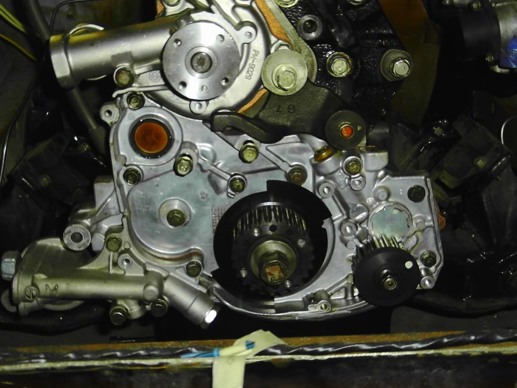
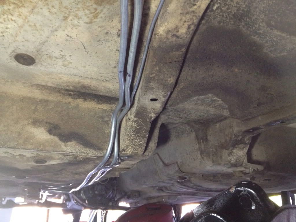
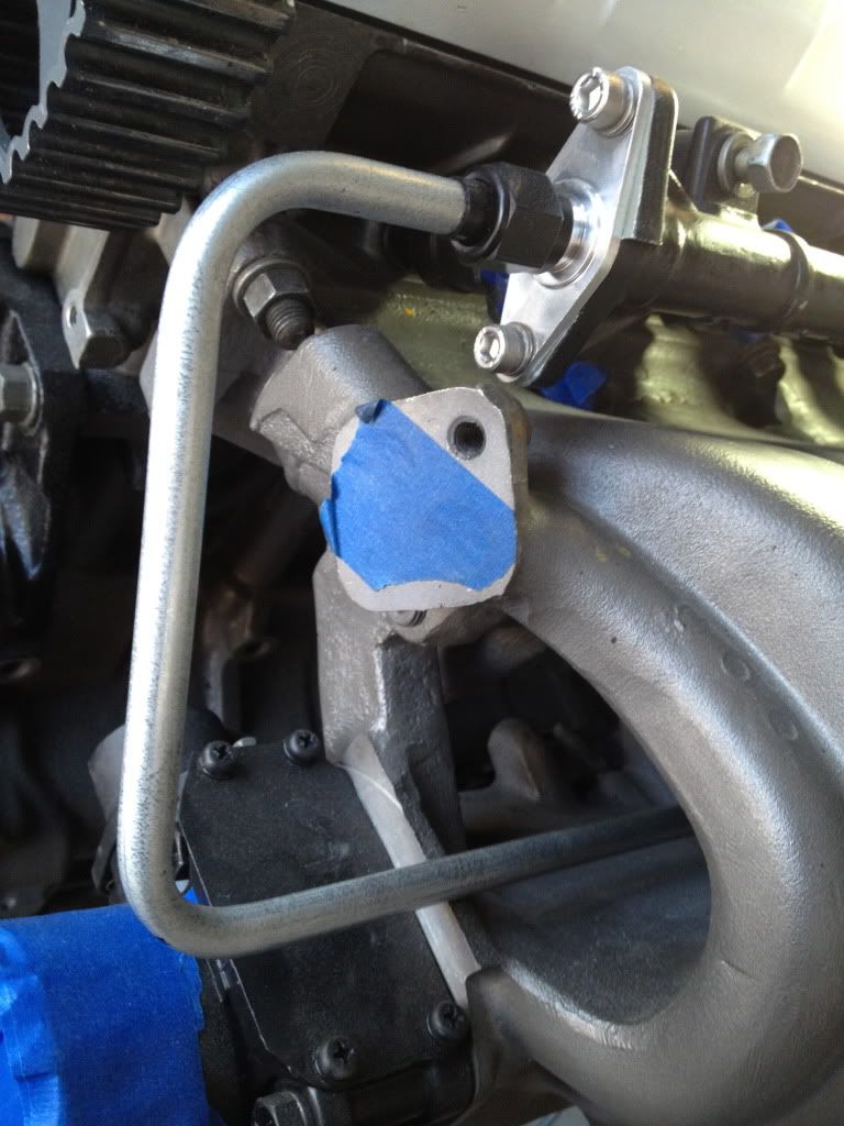
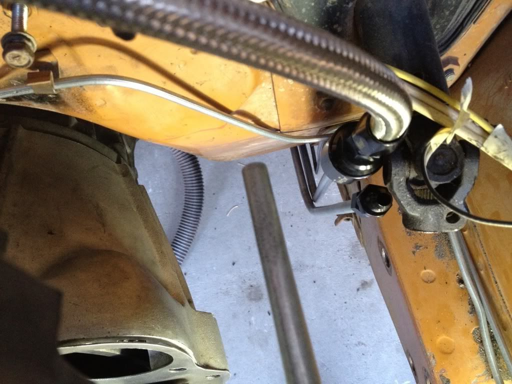
So I'm getting back to work on this thing a little at a time. My current issues are the water pump lines and fuel lines. I think I have the water pump thing figured out, but the fuel lines are a pain.
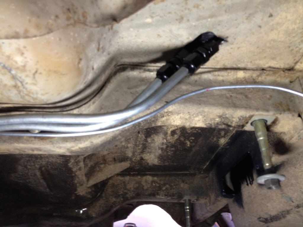
I bent up new brake lines without much issue, but the fuel lines are a pain. I'm using 3/8" standard steel line and I keep crushing the bends. I'm not sure what the issue is other than perhaps using a generic tubing bender that has a max tube diameter of 3/8".
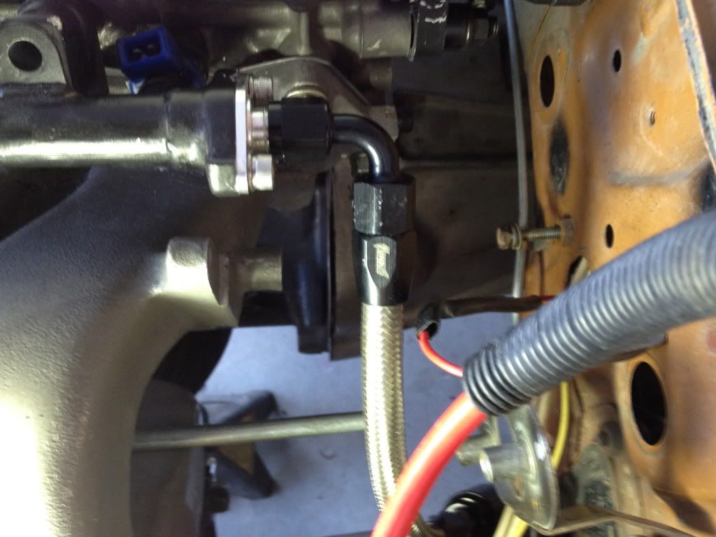
Is there a trick here? Should I step up to a big boy bender? The only other advice I've seen is putting sand into the line to keep it from crushing. Not sure if I want sand in my fuel lines. Any advice is welcome other than the use of braided line. I have limited space as it is and soft lines are not the answer anyway. Of course I'll be using braided line and AN fittings at junctions, so that's been covered. Let me know if anyone has advice or if there is a decent tutorial somewhere.
Posted: Sun Nov 20, 2011 8:20 pm
by screemin eagle
Get a spring bender. It's basically a coil that goes on the out side of the pipe where your bending it and keeps the pipe round.
http://www.homedepot.com/webapp/wcs/sto ... reNum=1950
Posted: Sun Dec 18, 2011 3:41 pm
by jeffball610
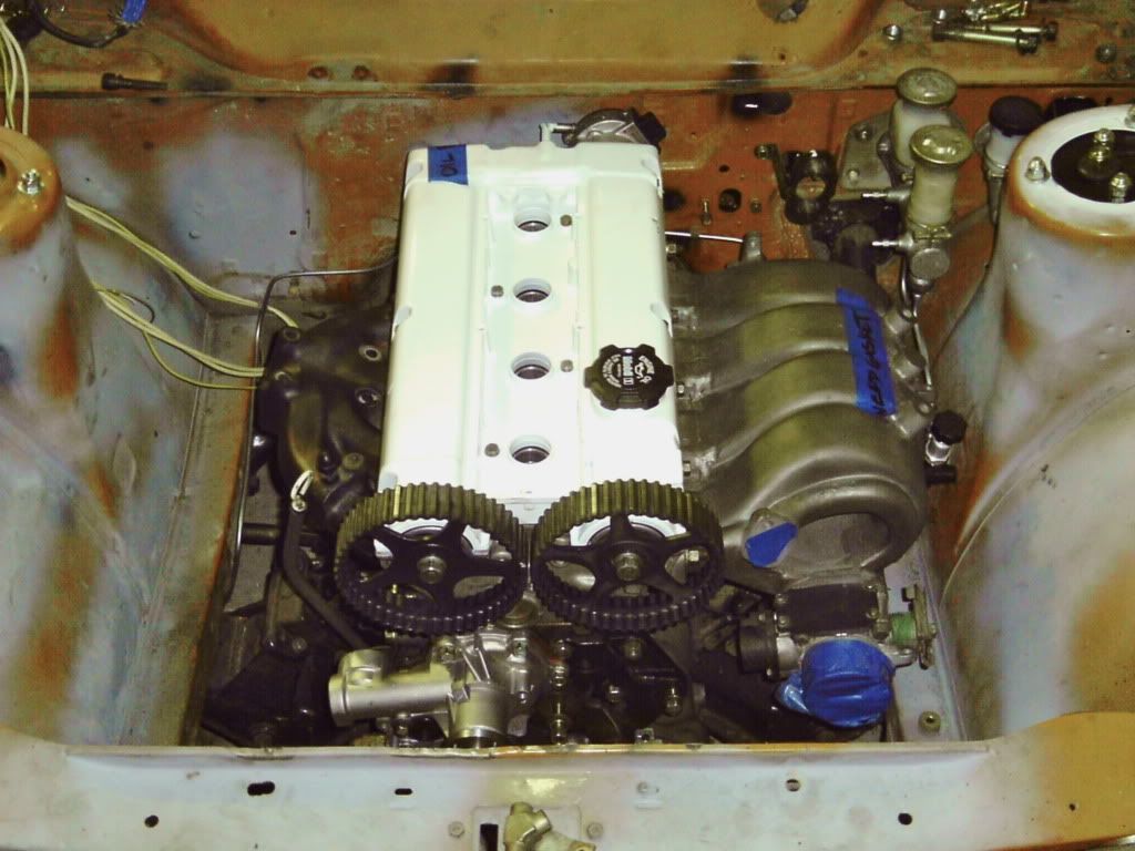
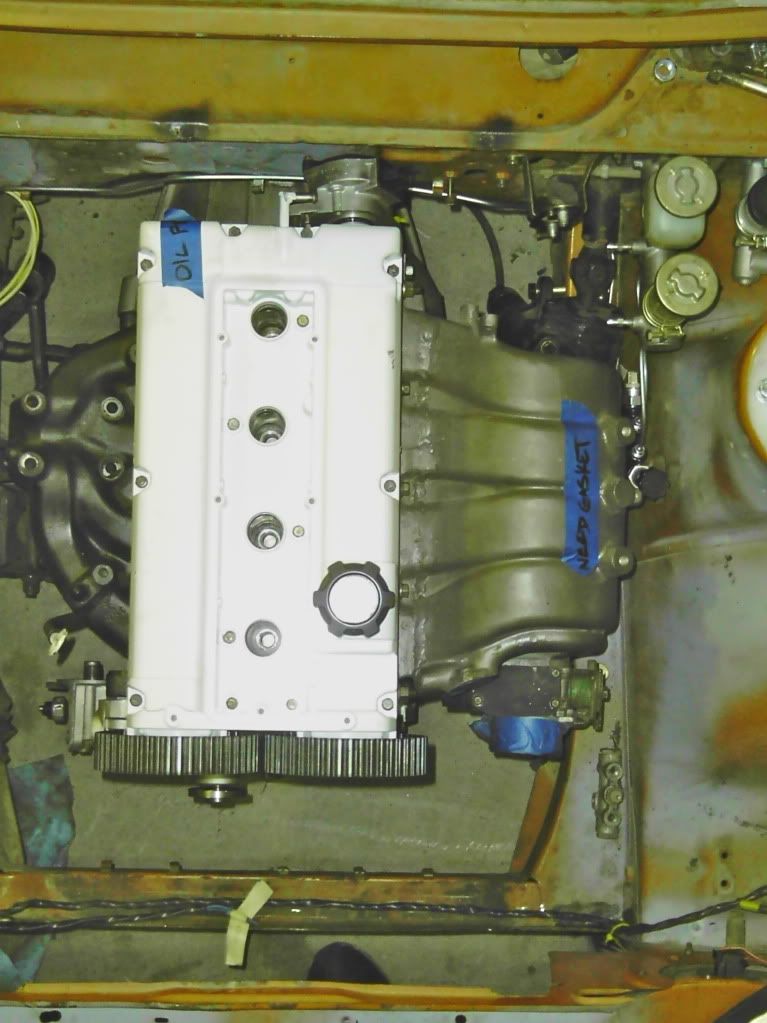
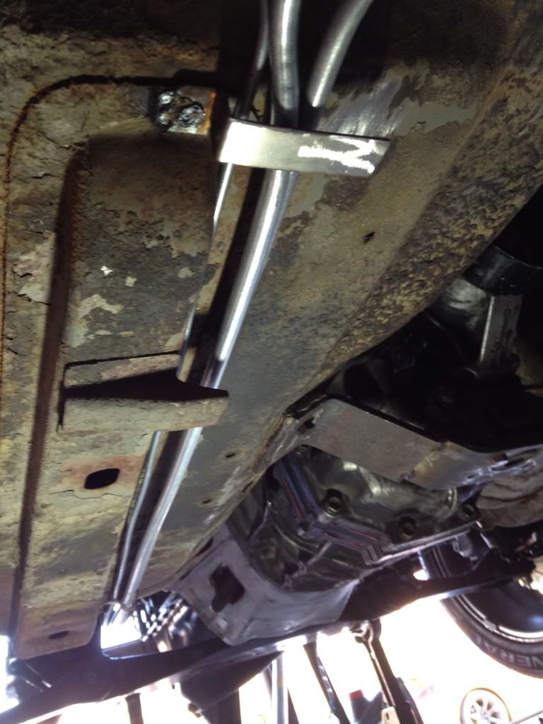
Things just got a little more complicated. I've been test fitting this motor and trans combo for some time now without issue. However, yesterday I added the clutch setup and went to install the whole assembly together. It doesn't fit as well as it had in the past.
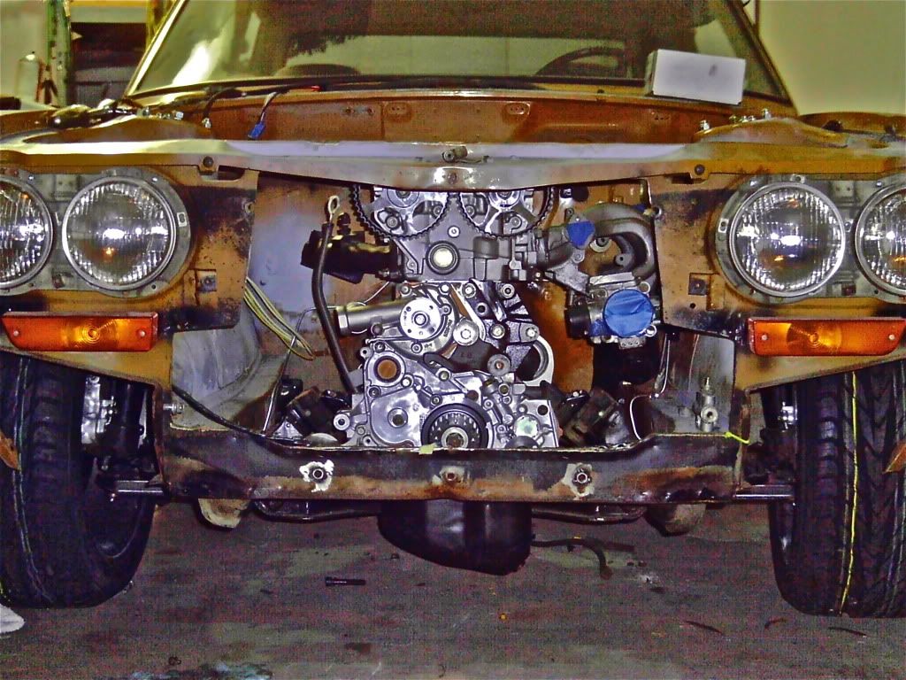
I decided to cut the front hood latch support to make it so I could install the engine and trans together. All went well until the thermostat housing hit the firewall. Less than a half inch of clearance makes it to where it doesn't want to go in the motor mounts. I had to install the motor mounts to the crossmember and then the motor itself to get in in the car. I will need to relief the firewall more to make this a little simpler. (and possible)
Anyone have ideas for making about a half inch of clearance other than just banging the sh!t out of the firewall? I might try to cut a small section and weld in a relief pocket. I'll take pics at some point to show what's happening.
Posted: Thu May 03, 2012 11:07 pm
by jeffball610
Posted: Thu Apr 17, 2014 7:16 pm
by jeffball610
I'm back! Just moved into a new place with a garage a month ago and getting things set up. Updates WILL be coming soon. Wiring is the first order of business. It's been 2 years without my car. I will have this thing on the road by the end of summer barring any major disasters.
Posted: Sun May 18, 2014 7:04 pm
by jeffball610
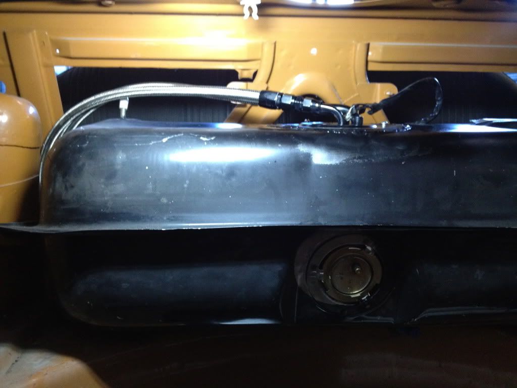
I promised some updates, and then forgot to post the small one from about 3 weeks ago. I finally got the fuel pump mounted in the stock tank. It's a Walboro 255lph on a Z31 fuel pump mount.
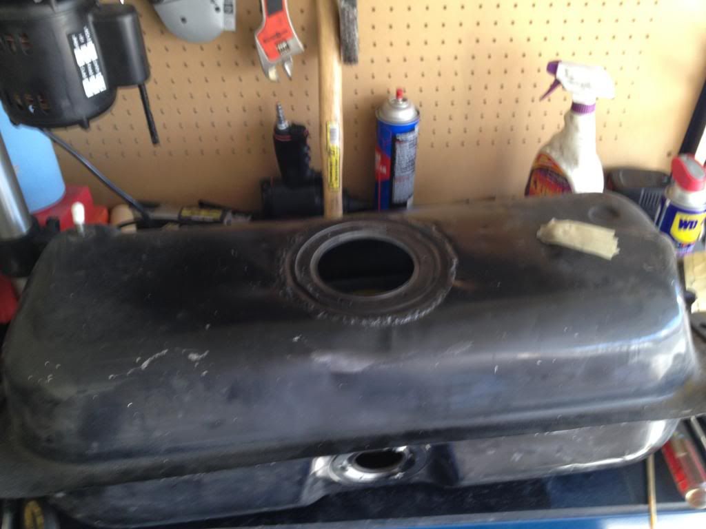
In hindsight, I should have done what everyone else does and mount it on the driver's side of the tank. It works in the middle, but I had to bend the fuel level sender to avoid the Z31 baffle-thing.
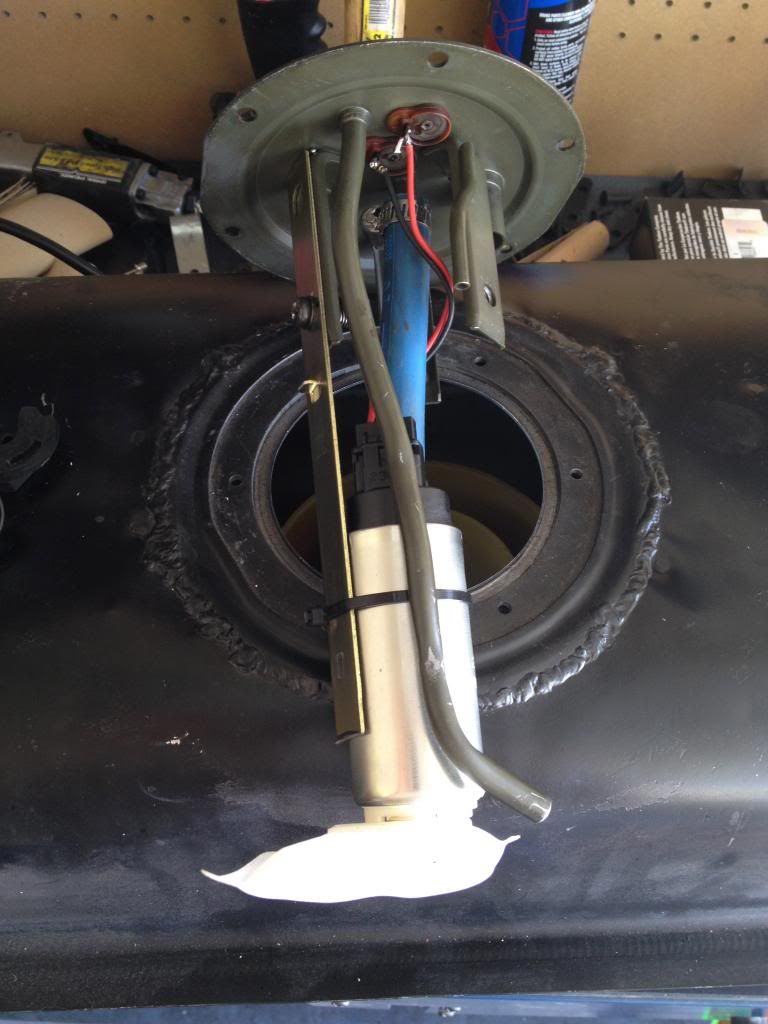
I did have to bend and cut the stock fuel return tube a bit. I also removed the stock fuel pump cage and just used one of the brackets to mount the pump. It also had to be shortened a bit. I did solder the wires to the stock location instead of splicing wires.
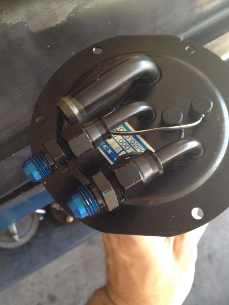
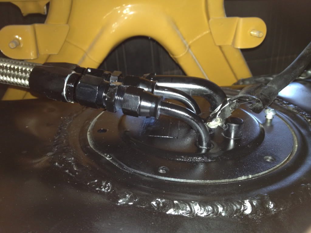
Here's the stock top with the hardline connectors. It's ready for a power connection.
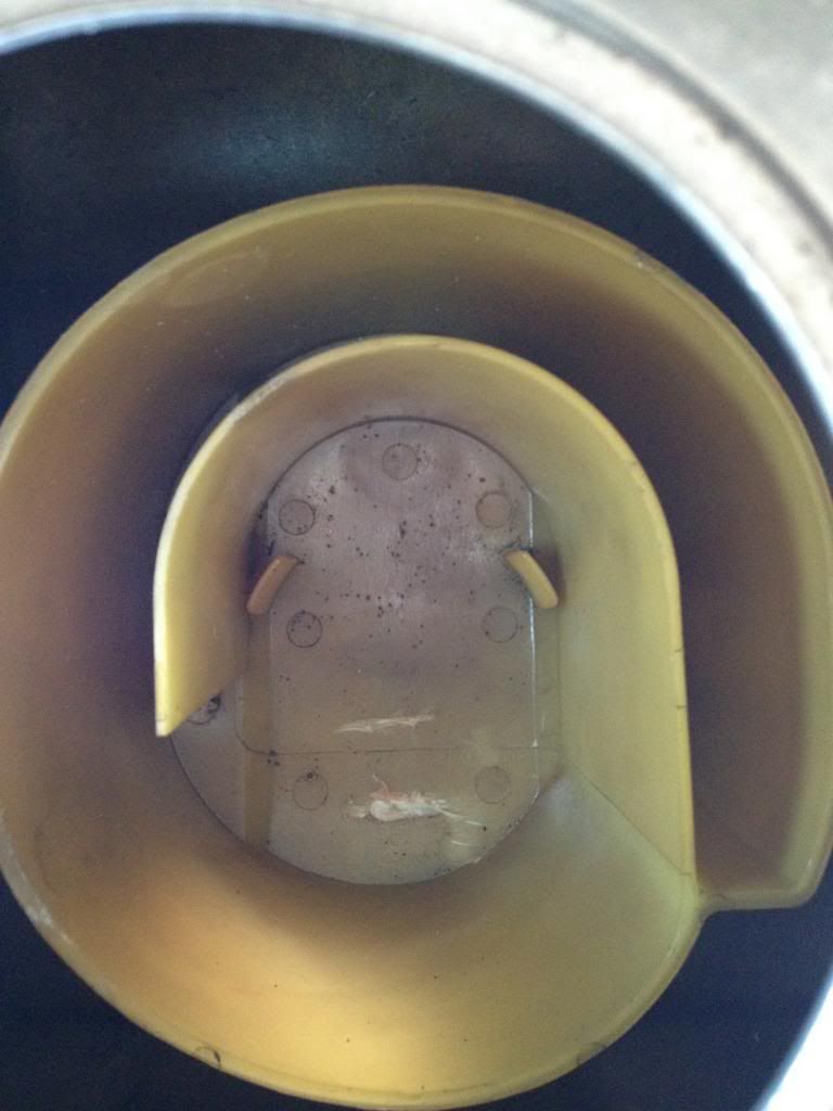
Here's the stock baffle-thing. It's pretty ingenious for a stock solution. I'm hoping it works out well for me. I did have to cut down one of the tabs in the bottom to clear the pump filter. They're there to hold the stock pump in the middle of the baffle.
I still need to get the proper o-ring for the top and find the correct screws to hold it down. I also need to seal up the unused tubes/holes in the tank and get the filler neck situation resolved. But hey, at least I got something done.

Posted: Tue Aug 19, 2014 10:43 pm
by jeffball610
Progress has been continuously halted by the confusing wiring process. I was working with a 95 Accord fuse/relay panel, and things just weren't making sense. Very little information exists on how to make it work with other vehicles. So I scrapped it and got a 2G NT fuse/relay pane (same as turbo, just a different shape)l. Room for 10 relays and 19 fuses. Should be plenty. It also makes a lot more sense and all of the relays work like normal, not like what I was dealing with the odd relays of the Honduh unit. I'm currently mapping the output wires and reconfiguring them to work with my harness. I've made more progress in one day with this than I did in months with the Honduh unit.
The only thing I can't figure out is the weird 1G Alternator relay situation. Bill tried to explain it, but it doesn't quite make sense. I'm flipping through wiring diagrams trying to see where the 3 wires go. I know white goes to the fuse panel at 80 amps and contacts the battery to charge it. The yellow wire (S-terminal) goes to the fuse panel for 30 amps, but not sure why. I assume the last wire (think it's black) goes to the dummy light. Anyone have more info on this circuit?
Edit: Just found this;
http://www.projectzerog.com/forum/viewtopic.php?t=2111
Doesn't really say what the wires do, but it appears that the WG wire (should be Yellow) is getting juice from the battery for some reason. The other wire seems to be the dummy light, but there's another resistor on a separate wire. Odd configuration. Is it needed to run?
Edit #2:
http://www.projectzerog.com/forum/viewtopic.php?t=1298
This says I don't need the dummy light wire. It says the S terminal is the "sense" wire, but if it's fused to the battery, won't it always see 12v? Also, I just realized the 1G uses an alternator relay. Looking at my fuse panel, it seems to only have 2 connections. How is that a relay?
Posted: Wed Aug 20, 2014 7:41 pm
by jeffball610
This isn't much help. Why are there so many different diagrams for the same thing and why can't I find the one I'm looking for?
Posted: Wed Aug 20, 2014 7:52 pm
by jeffball610
Bill shared this on Facebook. I think it makes sense now.

For those that can't read it:
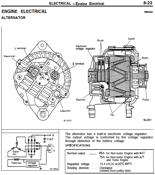
The "S" side is hot all the time from the fuse, then the ignition switch powers up the "L" side but only in the start position. That is the initial voltage input to the brushes to start the charging. When the switch reopens, (goes back to the on position) the diodes in the wiring system prevent voltage from flowing backwards.
Having voltage on both sides of the charging light keeps it "off" because you need ground present to turn the light "on". If the bulb finds ground on either side it will turn "on". With the "S" side powered up and after the brushes are excited by the "L" side briefly in the start position, then voltage flows to the load and to the batter from the "B" post of the alternator.
Because the voltage must exceed the batter voltage by 1v to force the flow of amperage to the batter, you should have a voltage reading of 14.5v at the battery in the run condition.
Posted: Tue May 31, 2016 7:48 pm
by jeffball610
I haven't posted any progress in a VERY long time. Life got in the way as it tends to do. I've made lots of progress and hope to be tearing up the road by the end of June.
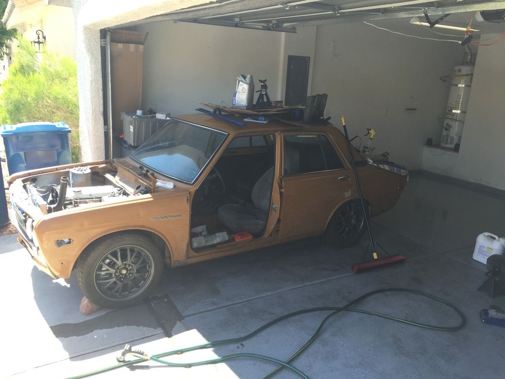
Getting some sun.
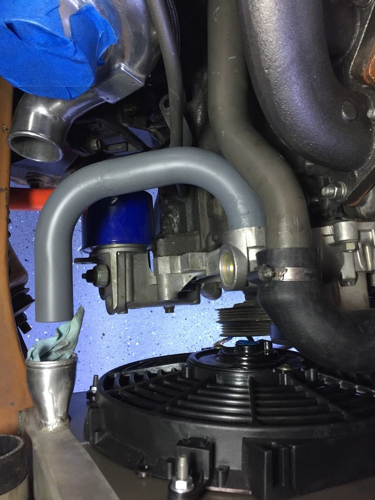
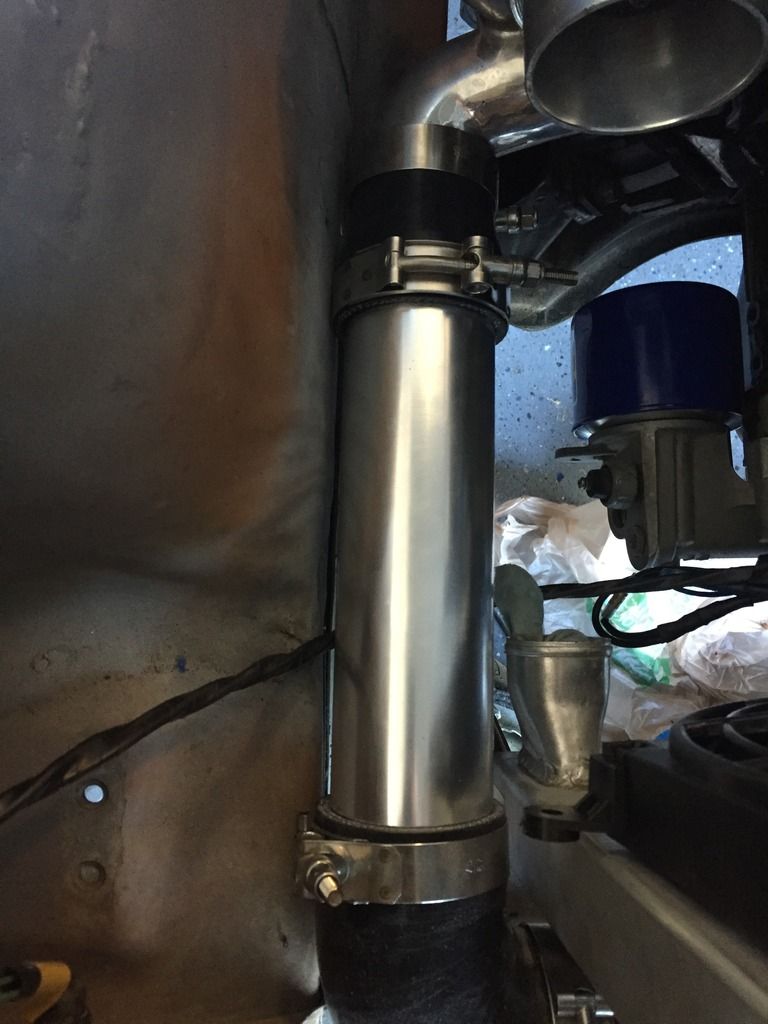
My lower coolant pipe.
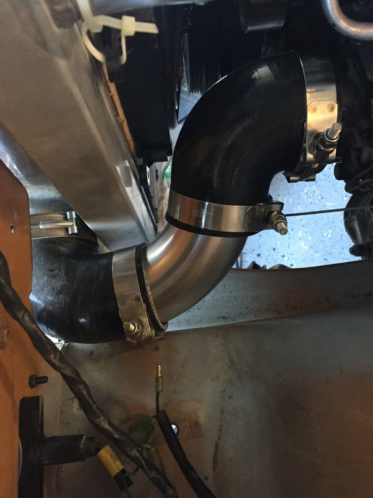
Terribly complex intercooler pipes
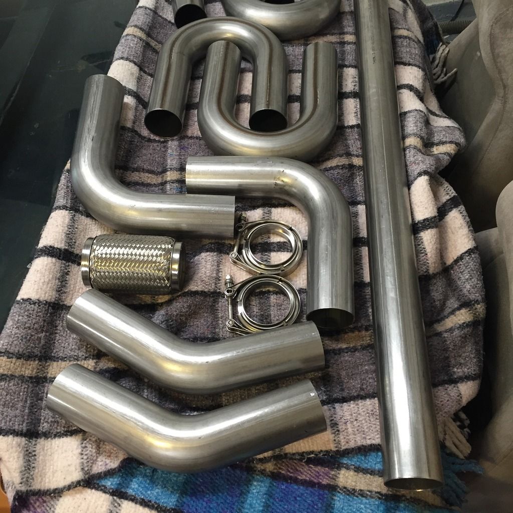
Exhaust parts. I'm getting it on a lift in 2 weeks to weld it into something that makes noise.
Lots more updates, but I'll hold off for now.
Posted: Sat Jul 16, 2016 11:47 am
by 4G-210
I admire your tenacity and patience. I could never have a project go this long without abandoning it. I did my build in about a year and it felt like it took forever.
Are you still trying to figure out the wiring? I have wired my datsun to use teh mitsubishi altenator. I could look at the wiring if you need. One wire is designed to sense overcharging, the rest are std stuff ie field and main wire on the large terminal.
Posted: Wed Aug 10, 2016 3:41 pm
by jeffball610
I've got just about everything done, but I can't get it to start. I have a thread in the Electrical section trying to figure out why.
I'm not getting spark or fuel for some reason. I'm trying to find a way to test the CAS to see if it's sending a signal. If it is, then I need to look at the ECU output and see if it's sending a signal to the injectors and coil. And on and on. I have an electrical engineer friend coming by this week (hopefully) to see if he can find my mistake or what the problem is. But at this point, it's basically road ready.
Posted: Mon Sep 19, 2016 7:11 pm
by jeffball610
I've been fighting a mess of wires trying to track down why it wouldn't start. Finally after offering a $100 reward, a friend stopped by to help out. Turns out I had a bad connector that tested good for continuity, but wasn't making good contact with the cam angle sensor. Now it makes great noises
 https://youtu.be/E2L0RLFbrCk
Next is to get it to idle. And then drive. And drive some more. And drive some more
[/url]
Posted: Sun Oct 30, 2016 2:13 pm
by jeffball610
Posted: Sun Oct 30, 2016 5:00 pm
by turbostellar
Congrats man. Sounds good
Posted: Wed Mar 29, 2017 10:17 pm
by jeffball610
It's been a while since my last update. The car runs and drives. i've put about 2.5 miles on it going up and down the street. I'm upgrading to speed density this week because my MAF doesn't like how it's mounted.
Other than that, I've been taking care of "safety" items to get it certified as road ready so I can register it. I've got a few small parts coming this week and it should make its public debut on April 8th at the weekly Saturday morning car meet.
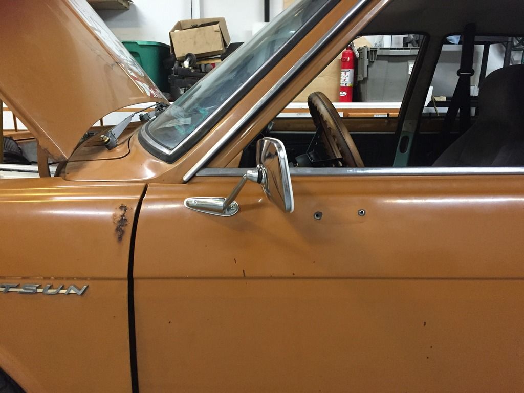
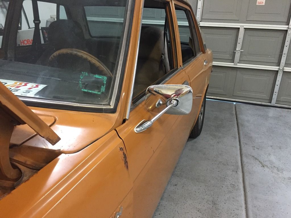
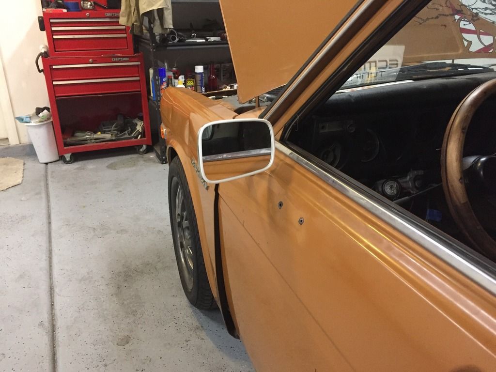
Here are the Taiwan "Datsun 521" mirrors I got. They're the best looking ones I could find at a decent price. I hate the white trim and gasket, but I need them to pass inspection and they're needed anyway with the idiots we have on the road.
Other than that, I've been doing small things. It has a Civic center console, functioning e-brake, upgraded to Marlin Crawler R154 shifter bushings, and I'll have some hood struts in this week along with windshield wipers that are needed for inspection.
Posted: Tue May 09, 2017 11:02 pm
by jeffball610
More pics to come soon, but thought I would drop a line to say my car is fully registered and passed smog in Nevada. I even got my custom plate that reads 4G6351O.
I haven't been too active on updates since it's been a lot of little things. I'm running ECMLink in speed density, but have had issues getting the wideband O2 to work, so I'm currently on the stock O2 sensor. It's running pretty decent, but I can tell it's running rich and is kind of lazy. I'm still breaking in the clutch and motor, so it's not much of an issue yet.
More updates to come along with some video. I'm hoping to participate in my first autocross on June 4th.
Posted: Mon Jan 01, 2018 10:49 pm
by jeffball610
Posted: Tue Jan 02, 2018 10:45 pm
by turbostellar
Looks awesome man, great work. Looking forward to seeing the progress
Posted: Thu Aug 02, 2018 5:35 pm
by jeffball610
CZeroMedia did a quick video about my car at Mitsubishi Owner's Day a few weeks ago and just posted the video.
https://youtu.be/Iq2nINNJIQ8
Posted: Mon Aug 06, 2018 10:35 am
by 71PMAM
You have gone and built yourself a sweet little car. I am curious whether you have had any dyno time yet. I know in the video yYou said that your trap time had you at 150 HP,but that seems very unlikely to me given the setup.
I admire the will that it takes to carry a build as long as you have to see it through. I hope that my build doesn't take so long,but that i attack it with at least half of your tenacity.