Intake Manifold Design Formula
Moderators: DJpowerHaus, mattmartindrift
-
jeffball610
- Too Much Time on His Hands
- Posts: 619
- Joined: Wed Feb 22, 2006 5:29 am
- Location: Las Vegas, NV
Intake Manifold Design Formula
I know I've seen one somewhere in a magazine. Maybe Sport Compact Car or something. I know there's a general formula for figuring out plenum size and runner length along with runner taper and such. I believe the general rule for plenum size is 1.5x engine displacement. I know runner length plays a role in where the engine makes power. Shorter runners for high end power and long runners for low end torque. I've decided the DSM intake isn't going to work for RWD modification although some have used it. Magnus and others are WAY over priced and I've been hearing of breakage issues with their sheet metal intakes. The guy I've been working with on alot of DSM stuff here locally is willing to make me a new manifold to my specs. He's very knowledgable and owes me. (I traded a AWD tranny and transfer case already) Anyone who knows this general formula or knows where it's at, let me know.
Re: Intake Manifold Design Formula
your a fool if you dont get the JMFabrications intake at $450. hell do it rwd to your specs. hes done a few that i know of and has 0 failure rates.jeffball610 wrote:I know I've seen one somewhere in a magazine. Maybe Sport Compact Car or something. I know there's a general formula for figuring out plenum size and runner length along with runner taper and such. I believe the general rule for plenum size is 1.5x engine displacement. I know runner length plays a role in where the engine makes power. Shorter runners for high end power and long runners for low end torque. I've decided the DSM intake isn't going to work for RWD modification although some have used it. Magnus and others are WAY over priced and I've been hearing of breakage issues with their sheet metal intakes. The guy I've been working with on alot of DSM stuff here locally is willing to make me a new manifold to my specs. He's very knowledgable and owes me. (I traded a AWD tranny and transfer case already) Anyone who knows this general formula or knows where it's at, let me know.
Re: Intake Manifold Design Formula
Whats his link or contact info. I will buy one.peregrine wrote:your a fool if you dont get the JMFabrications intake at $450. hell do it rwd to your specs. hes done a few that i know of and has 0 failure rates.jeffball610 wrote:I know I've seen one somewhere in a magazine. Maybe Sport Compact Car or something. I know there's a general formula for figuring out plenum size and runner length along with runner taper and such. I believe the general rule for plenum size is 1.5x engine displacement. I know runner length plays a role in where the engine makes power. Shorter runners for high end power and long runners for low end torque. I've decided the DSM intake isn't going to work for RWD modification although some have used it. Magnus and others are WAY over priced and I've been hearing of breakage issues with their sheet metal intakes. The guy I've been working with on alot of DSM stuff here locally is willing to make me a new manifold to my specs. He's very knowledgable and owes me. (I traded a AWD tranny and transfer case already) Anyone who knows this general formula or knows where it's at, let me know.
KILL
Re: Intake Manifold Design Formula
http://www.jmfabrications.com/catalog/p ... 6bb704a8d4tumuchNOS wrote:Whats his link or contact info. I will buy one.peregrine wrote:your a fool if you dont get the JMFabrications intake at $450. hell do it rwd to your specs. hes done a few that i know of and has 0 failure rates.jeffball610 wrote:I know I've seen one somewhere in a magazine. Maybe Sport Compact Car or something. I know there's a general formula for figuring out plenum size and runner length along with runner taper and such. I believe the general rule for plenum size is 1.5x engine displacement. I know runner length plays a role in where the engine makes power. Shorter runners for high end power and long runners for low end torque. I've decided the DSM intake isn't going to work for RWD modification although some have used it. Magnus and others are WAY over priced and I've been hearing of breakage issues with their sheet metal intakes. The guy I've been working with on alot of DSM stuff here locally is willing to make me a new manifold to my specs. He's very knowledgable and owes me. (I traded a AWD tranny and transfer case already) Anyone who knows this general formula or knows where it's at, let me know.
-
Bill Hincher
- Donating Member
- Posts: 1625
- Joined: Thu Jun 22, 2006 8:57 pm
- Location: Toledo,Ohio
- Contact:
hey jeff, take a look at this site, it has an adjustable animated venturi area that you can test how the air moves as you restrict the size and shape of a plenum http://home.earthlink.net/~mmc1919/venturi.html the only reason I suggest this site is because if you are going to have an inlet at one end of the plenum, the taper you want will be in the plenum and not the intake runners. As for a formula for the plenum size, my books show between 50% to 75% the cubic in displacement of the engine, I cant seem to find the exact formula

I took the time to cut up a stock 4G63 intake and the runners have no taper in them, the cylinder head provided the taper as it moved towards the intake valve
I took the time to cut up a stock 4G63 intake and the runners have no taper in them, the cylinder head provided the taper as it moved towards the intake valve
-
Robert Venable
- Donating Member
- Posts: 229
- Joined: Fri Sep 22, 2006 8:37 pm
- Location: BATON ROUGE, LA
-
Bill Hincher
- Donating Member
- Posts: 1625
- Joined: Thu Jun 22, 2006 8:57 pm
- Location: Toledo,Ohio
- Contact:
In the beginning, the word on "forced induction" motors was that the intake design wasn't especially important during in-boost situations. Particularly so if a surge tank was used.
The turbo gear heads seemed to have recently realized that forced induction motors really don't behave much differently than naturally aspirated motors, largely because they came to the understanding that there really wasn't any more "forcing" in "forced induction" than natural aspiration, hence the quotations around "forced induction." (it's simply a case of air moving from a higher pressure area to a lower pressure area in both instances).
^--------------------correct me if I'm wrong--------------------^
Still, I wonder if we really need to concern ourselves with the shape of the intake manifold and the formulas required to make one correctly. I think there are some things that should be taken good care to make "right": runner length, plenum size, throttle body size, transitions (big to small and variations). One thing to consider is we're still dealing with a "fluid" - air; so one must consider the bias of the fluid to flow to certain parts of the intake moreso than others (end up with unbalanced mixtures in the cylinders, for example). This is one reason end-tank design is so important, and there are so many cheap intercoolers out there with poorly designed and square/hard angle end-tanks that flow terribly and innefficiently (they don't use the whole intercooler, for example).
Again, I'm welcome to correction here as I'm still learning. The more I learn, the more I realize how much there is to know.
-
Bill Hincher
- Donating Member
- Posts: 1625
- Joined: Thu Jun 22, 2006 8:57 pm
- Location: Toledo,Ohio
- Contact:
Your point is well taken shaggy guy, the design of the plenum is not going to make the difference of a world beater vs a grocery getter. I would rather think its and excersise in learning. just pushing the design envelope.
A lot can be learned from the furnace industry, every home ( here) has a furnace, and the furnace is designed to deliver warm air through out the house equally and they all use a plenum to do that
The exact same thing is true of that plenum on your car, you want the same amount of air to arrive at each cylinder at the right time. Its a dry plenum because its fuel injected so lean conditions are not the issue, air distribution is.
Where it gets complicated is, when the intake valve shuts. Now that steady column of air is no longer flowing forward, it bounces backwards as an echo, well the organized column of air coming in from the plenum is still pushing forward and you should tune the length of the runners for where the two forces collide . ( ram tuning)
the other thing you have to keep an eye on is air speed, max air speed should be 700 FEET per second ( mach number) and the minimum would be 300 ft per second, ususally for that, you would design the runners at about 8.5 to .9 times the size of the intake valve, if you dont keep the speed up, you develop a bog or a turbo lag problem
I know, I know, I get tooooooooooo complicated, I am german
Good stuff. My only response is... I am German, too. 100% actuallyBill Hincher wrote:Your point is well taken shaggy guy, the design of the plenum is not going to make the difference of a world beater vs a grocery getter. I would rather think its and excersise in learning. just pushing the design envelope.
A lot can be learned from the furnace industry, every home ( here) has a furnace, and the furnace is designed to deliver warm air through out the house equally and they all use a plenum to do that
The exact same thing is true of that plenum on your car, you want the same amount of air to arrive at each cylinder at the right time. Its a dry plenum because its fuel injected so lean conditions are not the issue, air distribution is.
Where it gets complicated is, when the intake valve shuts. Now that steady column of air is no longer flowing forward, it bounces backwards as an echo, well the organized column of air coming in from the plenum is still pushing forward and you should tune the length of the runners for where the two forces collide . ( ram tuning)
the other thing you have to keep an eye on is air speed, max air speed should be 700 FEET per second ( mach number) and the minimum would be 300 ft per second, ususally for that, you would design the runners at about 8.5 to .9 times the size of the intake valve, if you dont keep the speed up, you develop a bog or a turbo lag problem
I know, I know, I get tooooooooooo complicated, I am german
-
jeffball610
- Too Much Time on His Hands
- Posts: 619
- Joined: Wed Feb 22, 2006 5:29 am
- Location: Las Vegas, NV
My main concern with the intake manifold is both size and shape. We need the right taper on the plenum, but also the runners. To increase volocity, don't we need to taper the runners down to the head? I keep refering to this "formula" that I saw. It experimented with the size of plenum based on this basic formula, but also ran different length runners and different tapers. I believe the taper was only about 15degrees on the runners. I'll keep searching. Keep pumping info into here. You never know when someone might need it.
The JMF units look nice and I might go that route. Right now I'm trying to get my money's worth from the parts I've traded to get this manifold made. So far I've traded: 91 AWD tranny and transfer case, (2) 1G throttle body elbows, 7-bolt AWD flywheel, a now hacked up 1G intake manifold, and he's lined up to get my 2.4L short block. For that price I better get a comprable manifold. My issue, like everyone, is a 4G63 manifold that fits between the shock towers as well.
The JMF units look nice and I might go that route. Right now I'm trying to get my money's worth from the parts I've traded to get this manifold made. So far I've traded: 91 AWD tranny and transfer case, (2) 1G throttle body elbows, 7-bolt AWD flywheel, a now hacked up 1G intake manifold, and he's lined up to get my 2.4L short block. For that price I better get a comprable manifold. My issue, like everyone, is a 4G63 manifold that fits between the shock towers as well.
-
Robert Venable
- Donating Member
- Posts: 229
- Joined: Fri Sep 22, 2006 8:37 pm
- Location: BATON ROUGE, LA
-
Bill Hincher
- Donating Member
- Posts: 1625
- Joined: Thu Jun 22, 2006 8:57 pm
- Location: Toledo,Ohio
- Contact:
down load java from here Bob,
http://www.java.com/en/download/index.jsp
http://www.java.com/en/download/index.jsp
-
Bill Hincher
- Donating Member
- Posts: 1625
- Joined: Thu Jun 22, 2006 8:57 pm
- Location: Toledo,Ohio
- Contact:
in the stock intake manifold , there are no tapers


from the intake manifold flange to the intake air plenum, there are no differences in the port area


However, the cone to the plenum is a taper, but it is a reverse taper, if I were to guess how this worked, I would say that the engineers wanted the air to travel quickly from the intercooler and then slow down as it dispersed into the plenum


In contrast the n/a 4G63 engine has a straight, flat intake at the throttle body, indicating no changes to incoming air flow


from the intake manifold flange to the intake air plenum, there are no differences in the port area
However, the cone to the plenum is a taper, but it is a reverse taper, if I were to guess how this worked, I would say that the engineers wanted the air to travel quickly from the intercooler and then slow down as it dispersed into the plenum
In contrast the n/a 4G63 engine has a straight, flat intake at the throttle body, indicating no changes to incoming air flow
-
jeffball610
- Too Much Time on His Hands
- Posts: 619
- Joined: Wed Feb 22, 2006 5:29 am
- Location: Las Vegas, NV
I know the stock intake manifold is a decent unit. Alot of guys still run them on their "street" cars with 400+hp. Most of the aftermarket stuff is meant for people who just want more top end power. The short runners help in that area. And since the engine in the DSM is so close to the firewall, you're kinda limited on manifold/runner size. That's another reason the stock unit is curved. I'm not arguing that the stock unit is bad or anything, I just need a manifold that will fit in my car and work properly. Reversing the thottle body on the stock manifold is a bad idea. If you look at Bill's cutaway, you'll notice how the plenum is smaller on the #1 cylinder side. Some people have just welded or cut and welded the TB onto that end, and probably are suffering some loss of power due to it. Or at least some trouble in tuning. The JMF, Forrester, BJ, Magnus etc manifolds are nice and great for drag racing, but I want something that works as well as the stock unit in a RWD configuration. Maybe I'm just asking too much.
The TB elbow on the 1G is a terrible restriction in flow. I won't know why the "engineers" did this. Just putting on an aftermarket upper intercooler pipe (UIP) you'll have a noticable increase in air flow. These DSMs are great. Just put an K&N, intercooler pipes, exhaust, fuel pump, boost controller and fuel control and you can theoretically run 12's on a 1G AWD.
http://www.dsmtuners.com/forums/showthread.php?t=60008
Is this by our same Peregrine?
I've been going back and forth on either doing a custom intake manifold or relocating my brake master cylinder in order to fit the m/c in combination with the booster (currently I run the m/c alone).
What if the runners were angled in order to allow them to be longer and still clear everything, like the stock intake? Is there a negative effect on having the runners angled? I notice all the aftermarket ones have straight runners. Is it true that the shorter runners hurt the low rpm power?
Apart from the possible extra areas for air leakage (probably not a problem with t-bolt clamps) this is a cool idea for adjusting for power and/or engine bay clearance: http://www.jmfabrications.com/images/sm ... take20.jpg
-
Bill Hincher
- Donating Member
- Posts: 1625
- Joined: Thu Jun 22, 2006 8:57 pm
- Location: Toledo,Ohio
- Contact:
turbo lag is a problem with a large plenum because it takes more work from the turbo to fill the extra space
Because this is a dry plenum ( air only) it makes no difference what direction the air flows, it can be up down, sideways , the air dont care

the only time your runners are working is when the engine is NOT using the turbo

shorter runners will work , but the camshaft must be changed with it

A great deal of attention must be paid to the intake opening event to time the organized air to be at the intake valve at the right time

As you can see this whole event is timed to the crankshaft, camshaft at a given RPM so if you change your cam , you should be using a crankshaft degree wheel to time all these events to its maximum use
Because this is a dry plenum ( air only) it makes no difference what direction the air flows, it can be up down, sideways , the air dont care
the only time your runners are working is when the engine is NOT using the turbo
shorter runners will work , but the camshaft must be changed with it
A great deal of attention must be paid to the intake opening event to time the organized air to be at the intake valve at the right time
As you can see this whole event is timed to the crankshaft, camshaft at a given RPM so if you change your cam , you should be using a crankshaft degree wheel to time all these events to its maximum use
-
jeffball610
- Too Much Time on His Hands
- Posts: 619
- Joined: Wed Feb 22, 2006 5:29 am
- Location: Las Vegas, NV
Actually Bill, we use adjustible cam sprokets to time the crank and cam timing together. I sould think angling the intake would be good. You would have to know the entry angle to optimize it. I think the aftermarket intakes have straight runners cause they're lazy and don't want to bend tube to make nice runners. However, if you look at Edlebrock intakes for Honduhs, they're nice and cast with stock-like design. I would say the best idea is to find a good runner length and bend tube to clear the engine bay obstacles like the stock design. I think keeping the entry as a straight shot would also be best instead of an angled approach. This is all theory though. I'm still looking for that formula and hope to have some answers soon.
-
Bill Hincher
- Donating Member
- Posts: 1625
- Joined: Thu Jun 22, 2006 8:57 pm
- Location: Toledo,Ohio
- Contact:
I can alter how much length you need for intake runner by opening the intake valve a little later, but your duration is going to change valve overlap, so if I can find the right cam with a higher speed ramp and later timing, I can shorten the intake and put a small taper in it to bring up the air speed
those longer runners are trying to 'stack' the revesions on top of each other to time the fourth or fifth wave of reversion where the air speed gains the most momentum
the formula for that is
2nd wave
length of runner in inches=108,000 divided by RPM
3rd wave
length of runner in inches= 97000 divided by RPM
4th wave
length of runner in inches=74000 divided by RPM
5th wave
length of runner in inches =54000 divided by RPM
it obvious that the second wave is much stronger , but the length of the runner is outta site

This is Chryslers famous attempt to harness the first and second wave in the induction cycle
those longer runners are trying to 'stack' the revesions on top of each other to time the fourth or fifth wave of reversion where the air speed gains the most momentum
the formula for that is
2nd wave
length of runner in inches=108,000 divided by RPM
3rd wave
length of runner in inches= 97000 divided by RPM
4th wave
length of runner in inches=74000 divided by RPM
5th wave
length of runner in inches =54000 divided by RPM
it obvious that the second wave is much stronger , but the length of the runner is outta site
This is Chryslers famous attempt to harness the first and second wave in the induction cycle
-
Bill Hincher
- Donating Member
- Posts: 1625
- Joined: Thu Jun 22, 2006 8:57 pm
- Location: Toledo,Ohio
- Contact:
-
jeffball610
- Too Much Time on His Hands
- Posts: 619
- Joined: Wed Feb 22, 2006 5:29 am
- Location: Las Vegas, NV
Found a little info from a Dejon Powerhouse intake.
http://dsm.dejonpowerhouse.com/edit/1-01.htm
No info here, but some close-up pics for reference.
http://www.magnusmotorsports.com/intake ... ds/dsm.htm
Jackpot! Just found this. Done by some of my friends in Colorado!
http://206.124.12.138/intake/
http://dsm.dejonpowerhouse.com/edit/1-01.htm
No info here, but some close-up pics for reference.
http://www.magnusmotorsports.com/intake ... ds/dsm.htm
Jackpot! Just found this. Done by some of my friends in Colorado!
http://206.124.12.138/intake/
I have a 61 300 buddy, but I have never driven it as the motor is apart. My dad has and he said that it was really spry for being such a big heavy car because of the huge torque on the bottom. Its weird that you picked the old longhorn/ram for an example, I though maybe you would show the first "Ramchargers" manifold from the Coupe (ten stories highBill Hincher wrote:I can alter how much length you need for intake runner by opening the intake valve a little later, but your duration is going to change valve overlap, so if I can find the right cam with a higher speed ramp and later timing, I can shorten the intake and put a small taper in it to bring up the air speed
those longer runners are trying to 'stack' the revesions on top of each other to time the fourth or fifth wave of reversion where the air speed gains the most momentum
the formula for that is
2nd wave
length of runner in inches=108,000 divided by RPM
3rd wave
length of runner in inches= 97000 divided by RPM
4th wave
length of runner in inches=74000 divided by RPM
5th wave
length of runner in inches =54000 divided by RPM
it obvious that the second wave is much stronger , but the length of the runner is outta site
This is Chryslers famous attempt to harness the first and second wave in the induction cycle
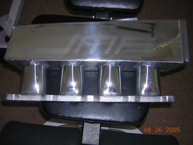
I ordered a JM manifold (cool guys to deal with) and it should be here next week. I will post up if made a huge change in how the car runs given the fairly large plenum and short runners (packaging issues). It should kill some torque on the bottom and pick up quite a bit on top.
KILL
-
Bill Hincher
- Donating Member
- Posts: 1625
- Joined: Thu Jun 22, 2006 8:57 pm
- Location: Toledo,Ohio
- Contact:
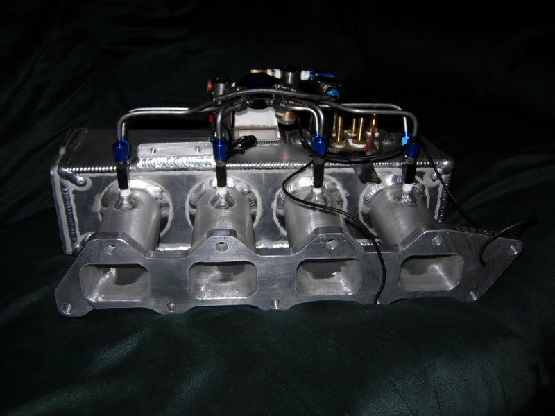
you know whats wrong with this picture?
they keep bringing the plenum upwards
If you look at DJ's car your gonna see the plenum up too high to receive the outlet from the heat exchanger
the longer intake runners are free horsepower, yeah, you can go to shorter runners and change where the horsepower works at higher RPM, but that long runner dont cost a cent for HP especailly under boost.
why not take an intake flange and set a plenum low and forward ( you got lots of room forward) then build the runners down instead of up and keep them as long as possible. It would be easy to compensate the volume of the plenum by its diameter, in order to move it from front to back
that way you could take out the big bend in the tubing at the front of the throttle body from the heat exchanger and shorten the length the air has to travel at the same time, you know, if you are going to run an air flow meter, the action between the throttle body and the air flow meter slows down because of how far it has to travel, and turbo lag is a problem because you are filling more volume before the air spools up to boost
it seems like a good move all way around
I know this thread is dead, but I finnally got motivated enough to start the mock up for the new intake. JMF built it off of my measurements, and it fits great. My only real problem is the interference with my clutch cable where it exits the firewall. Hopefully Mr bill will finish his T56 Bell soon and I can switch to a hydro set up and justify the FAB 9 I want to throw under it.
Anyways heres Johnny...
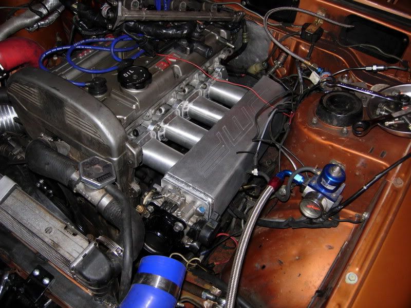


Anyways heres Johnny...
KILL
-
Bill Hincher
- Donating Member
- Posts: 1625
- Joined: Thu Jun 22, 2006 8:57 pm
- Location: Toledo,Ohio
- Contact:
-
Robert Venable
- Donating Member
- Posts: 229
- Joined: Fri Sep 22, 2006 8:37 pm
- Location: BATON ROUGE, LA
-
Bill Hincher
- Donating Member
- Posts: 1625
- Joined: Thu Jun 22, 2006 8:57 pm
- Location: Toledo,Ohio
- Contact:
I've been wondering that myself, Bill. So many foiks are willing to make dirty exhaust manifolds or really pretty ones and find that it's not terribly difficult to do either. I'm curious, though, if designs like this fancy manifold are just a "safe" design to use.Bill Hincher wrote:why hasnt anybody built a plenum like a hedder, only in reverse? why does the plenum have to be placed in a way the air has to bend at a 90 degree angle? isnt that just for packaging in a FWd set up?
I don't think anyone expects to have all the calculations for a correctly sized intake manifold for their application and power desires. However, I think there can be more variances than what we've been seeing.
(I'm tired and what I just wrote looks bizarre)
-
jeffball610
- Too Much Time on His Hands
- Posts: 619
- Joined: Wed Feb 22, 2006 5:29 am
- Location: Las Vegas, NV
-
Robert Venable
- Donating Member
- Posts: 229
- Joined: Fri Sep 22, 2006 8:37 pm
- Location: BATON ROUGE, LA
-
jeffball610
- Too Much Time on His Hands
- Posts: 619
- Joined: Wed Feb 22, 2006 5:29 am
- Location: Las Vegas, NV
Finally after doing some random searching I found an article on intake manifold design. It is 4G63 specific and also goes into head flow. I haven't gone back and read all of it, but it seems like this was the article I was searching for.
http://www.dsmtuners.com/forums/article ... -long.html
http://www.dsmtuners.com/forums/article ... -long.html
-
DJpowerHaus
- Sir Post A Lot
- Posts: 1779
- Joined: Wed Apr 07, 2004 3:24 pm
- Location: Baltimore, MD
- Contact:

-
Robert Venable
- Donating Member
- Posts: 229
- Joined: Fri Sep 22, 2006 8:37 pm
- Location: BATON ROUGE, LA
-
screemin eagle
- Too Much Time on His Hands
- Posts: 355
- Joined: Thu Feb 03, 2005 1:50 am