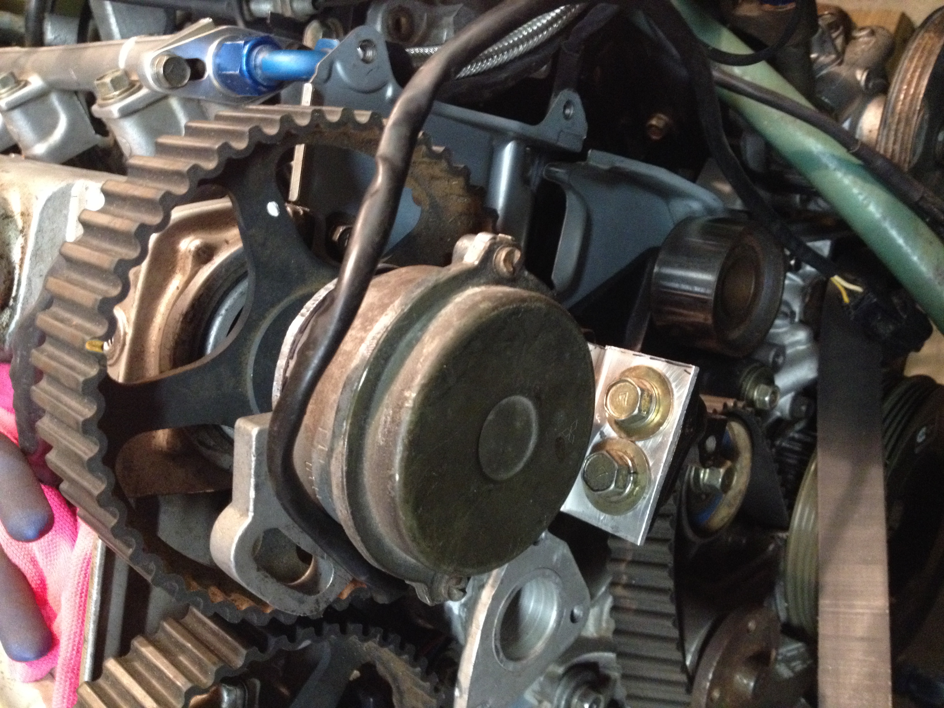
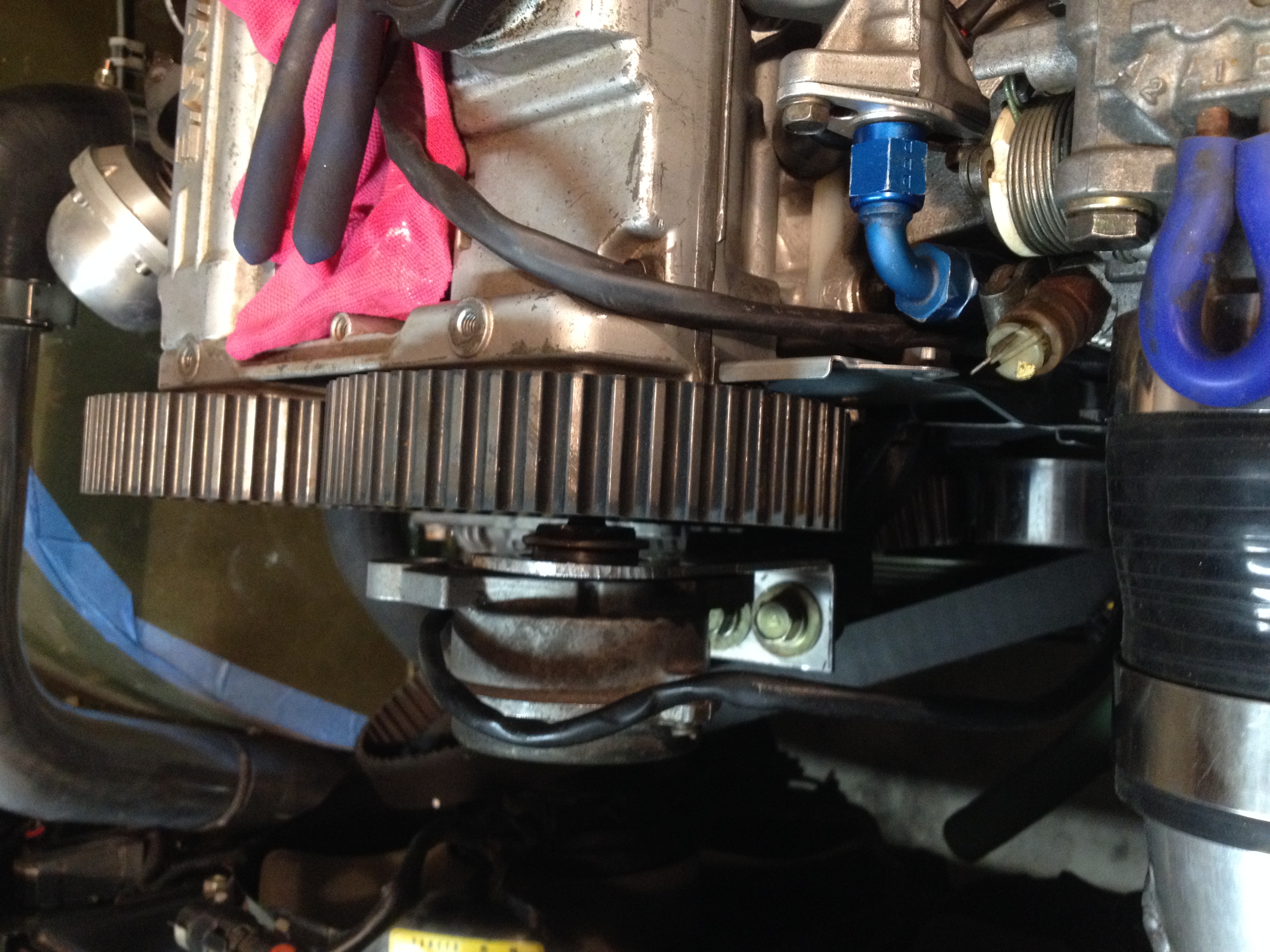
custom laser cut trigger disk
mounting bracket
coupling bolt for cam gear.
Making a bracket and coupling seems easy enough.(sorry for big sideways pictures)

Now I really want to figure out this trigger disc.
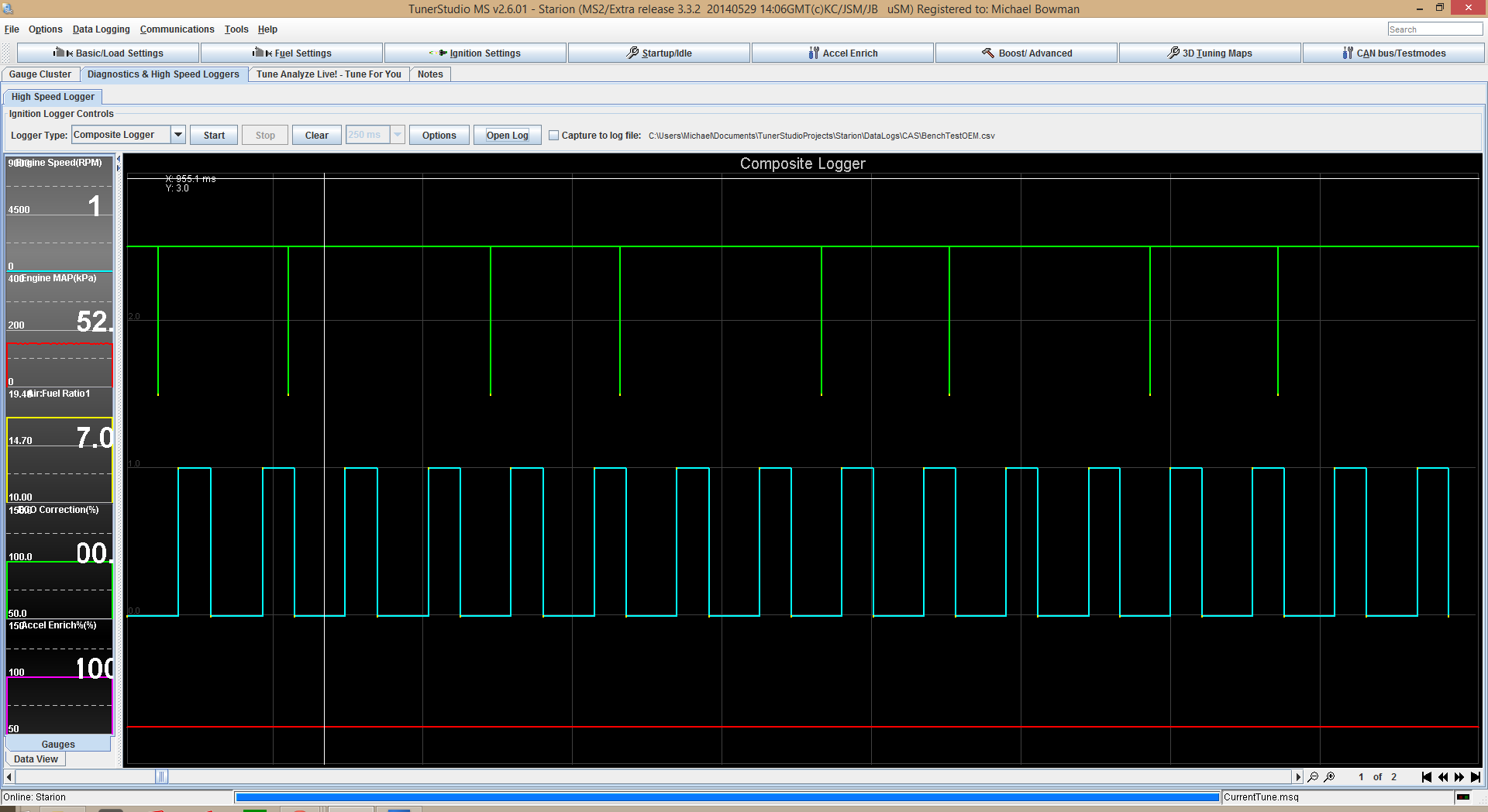
Using the composite logger I have logged the OEM sensor spinning the stock direction which recognized the correct rpm as expected with no sync errors:
Tuner Studio Log File
http://projectzerog.com/images/members/ ... estOEM.csv
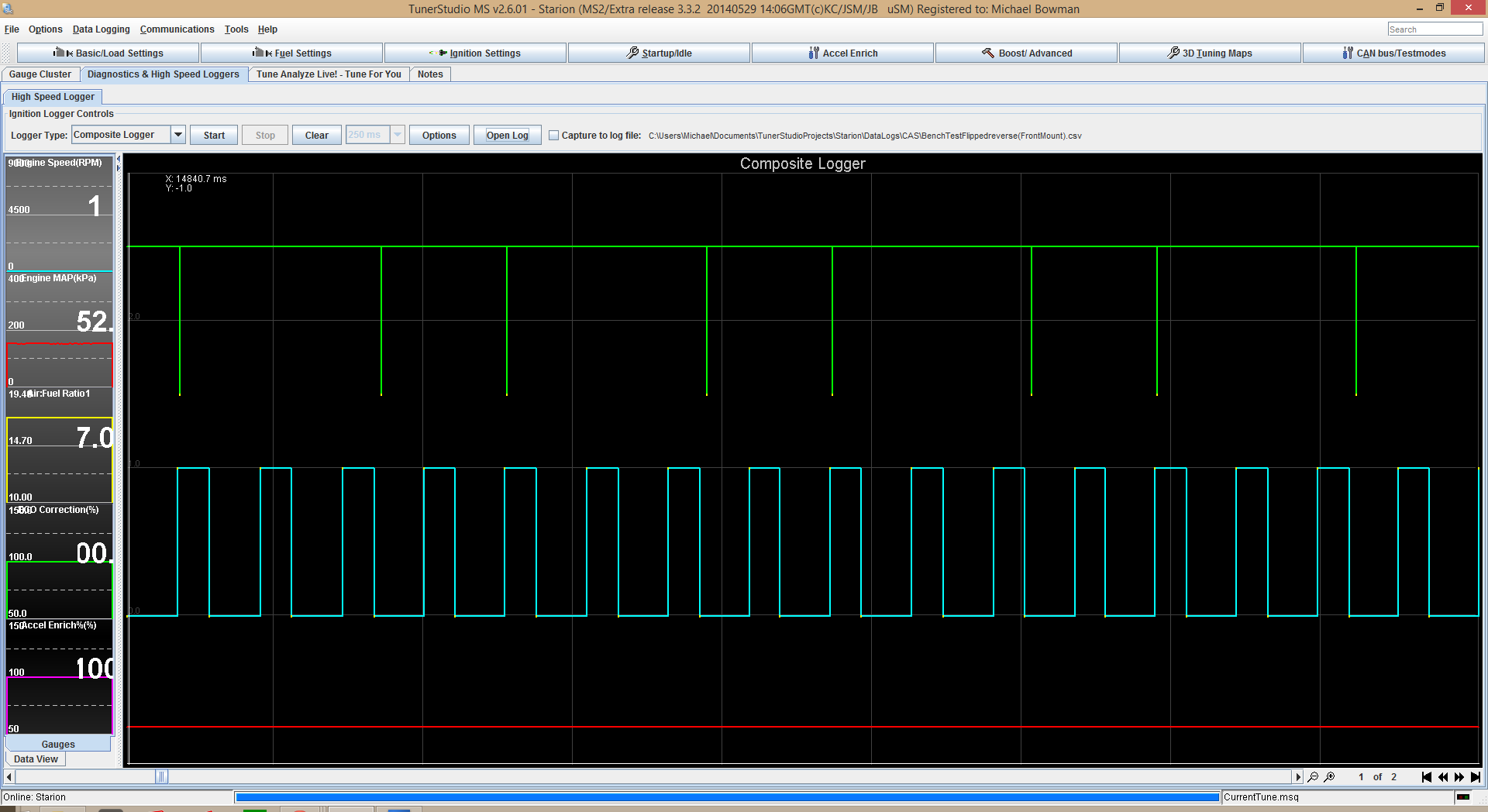
I've also logged the sensor spinning backwards with the disc flipped and the MS recognized the correct RPM with no sync errors.
Tuner Studio Log File:
http://projectzerog.com/images/members/ ... Mount).csv
Comparing the two however reveals that the signals do not match, one is offset, most likely do the the offset of LEDs in the Mitsubishi CAS.
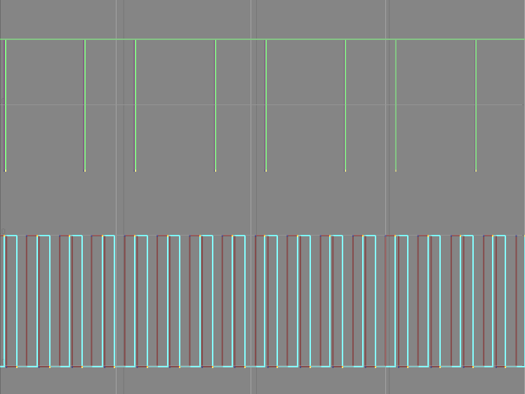
Can I correct this offset with any settings in Tunerstudio?
Ideally, I'd like to solve it by having new trigger discs laser cut so that it will work with the OEM ECU. I scanned the trigger disc into the computer at the highest resolution possible and traced it out in Sketchup (I <3 Sketchup).
Scanned CAS trigger (8mb):Click to Download
Sketchup Drawing: Click to Download
I can export it as a .dxf to laser cut at the local hacker space (Baltimore Node). First I need to figure out what I need to do to modify it. I can rotate the 4 outer trigger slots relative to the center key as well as the inner trigger slots to .1 degree in Sketchup. How can I figure out how many degrees and which direction?
Any help would be great.

