Well, I'm getting to that point and need some clarification. I thought the BW wire from the ECU and MPI Relay sent power to the fuel pump, but I want to make sure I'm getting enough power. The old DSM trick was to put a dedicated power wire to the fuel pump with a relay near the pump. Is this still necessary? I'm running a 10 gauge wire from the ECU to the fuel pump.
Should I stick with a lighter gauge wire as a signal wire and run a dedicated fused wire through a relay and then to the pump? I thought the original issue was that Mitsu used light gauge wires and this was just a fix so you didn't have to splice into the ECU area. Since I'm running wires on my own, will it send the required 14v from the ECU and MPI Relay all the way to the pump?
Fuel Pump Wiring
Moderators: DJpowerHaus, mattmartindrift
-
jeffball610
- Too Much Time on His Hands
- Posts: 619
- Joined: Wed Feb 22, 2006 5:29 am
- Location: Las Vegas, NV
Fuel Pump Wiring
Do it in a Datsun!
1972 Datsun 510
7-bolt 4G63T, EVO 9 pistons and rods, Garrett GT3076R, "flipped" stock intake, Toyota R154, Z31 R200 w/ CVs
1972 Datsun 510
7-bolt 4G63T, EVO 9 pistons and rods, Garrett GT3076R, "flipped" stock intake, Toyota R154, Z31 R200 w/ CVs
-
jeffball610
- Too Much Time on His Hands
- Posts: 619
- Joined: Wed Feb 22, 2006 5:29 am
- Location: Las Vegas, NV
-
DJpowerHaus
- Sir Post A Lot
- Posts: 1779
- Joined: Wed Apr 07, 2004 3:24 pm
- Location: Baltimore, MD
- Contact:
Reducing losses caused by a 1 volt drop in the wiring is helpful in getting a few more gph out of a fuel pump, but using a decent high flow fuel pump works too.

Getting the engine bolted in is about 10% of the way there.
The next 80% can go quickly with help and skill.
That last 10% takes about as long as the 90% that came before it.
-
jeffball610
- Too Much Time on His Hands
- Posts: 619
- Joined: Wed Feb 22, 2006 5:29 am
- Location: Las Vegas, NV
Thanks for the response, but it doesn't help answer the question. I know the original 1G stuff was meant to increase performance over the stock wiring. But I don't know if the ECU is sending out the same voltage I can get from running a separate wire. I'll keep searching and see if I can get an answer for all of us. I'm not desperate for that 1v, but I'd rather not have to put wiring in the car after this.
Do it in a Datsun!
1972 Datsun 510
7-bolt 4G63T, EVO 9 pistons and rods, Garrett GT3076R, "flipped" stock intake, Toyota R154, Z31 R200 w/ CVs
1972 Datsun 510
7-bolt 4G63T, EVO 9 pistons and rods, Garrett GT3076R, "flipped" stock intake, Toyota R154, Z31 R200 w/ CVs
-
Bill Hincher
- Donating Member
- Posts: 1625
- Joined: Thu Jun 22, 2006 8:57 pm
- Location: Toledo,Ohio
- Contact:
the ECU is not made to carry the load the fuel pump will devlop, its all done through the main relay
The ECU signals the main relay to run when the key is in 'start' position or 'run' position but not run if the engine is not running, its a saftey so the engine doesnt flood

just use a digital volt meter and place it across the power outlet ( ign1 @ the ignition switch) and to the input of the fuel pump ( B/W wire) WHILE THE FUEL PUMP IS RUNNING and if it measures any voltage , then that is how much energy ( voltage) that was required to run the relay
The ECU signals the main relay to run when the key is in 'start' position or 'run' position but not run if the engine is not running, its a saftey so the engine doesnt flood
just use a digital volt meter and place it across the power outlet ( ign1 @ the ignition switch) and to the input of the fuel pump ( B/W wire) WHILE THE FUEL PUMP IS RUNNING and if it measures any voltage , then that is how much energy ( voltage) that was required to run the relay
-
jeffball610
- Too Much Time on His Hands
- Posts: 619
- Joined: Wed Feb 22, 2006 5:29 am
- Location: Las Vegas, NV
So I guess the real question is can the ECU send enough voltage AND amperage to the fuel pump without a separate relay?
I've looked over that, and many other wiring diagrams several times and there is nothing to lead me to believe there is a separate relay or wiring system in the stock wiring. The main reason I asked this question was that the old trick of wiring in a relay to help send "extra" voltage to the fuel pump is always recommended. However, I think this was simply due to the size of the stock wiring rather than the ECU being capable of sending the proper voltage.
So based on what I see here and what I believe to be true, I will simply send power from the stock ECU/MPI pinouts to the fuel pump. If I'm wrong and it needs more power later, I will just add a relay like they always have in DSMs. I just hope I don't have to.
Do it in a Datsun!
1972 Datsun 510
7-bolt 4G63T, EVO 9 pistons and rods, Garrett GT3076R, "flipped" stock intake, Toyota R154, Z31 R200 w/ CVs
1972 Datsun 510
7-bolt 4G63T, EVO 9 pistons and rods, Garrett GT3076R, "flipped" stock intake, Toyota R154, Z31 R200 w/ CVs
-
Bill Hincher
- Donating Member
- Posts: 1625
- Joined: Thu Jun 22, 2006 8:57 pm
- Location: Toledo,Ohio
- Contact:
the ECU NEVER sends power to anything, it only sends grounds
in order to maintain a constant voltage ( because the voltage is different when charging) the ECU has a built in voltage regulater, it runs on 4.25 volts ( Vref)
as sensers get old and resitance to voltage increases the Vrev ( 4.25 volts) will increase to allow the engine to run properly, this is called 'adaptive straitigies'
once the resitance crosses the threshold of 4.7 volts, then the computer needs to replace worn sensers and 're-learn' to use 4.25 v
so you can determine where your wear stage is at by measuring how much Vrev your computer needs to run the engine
the fuel injecters and fuel pump and all the driven components by the ECU recieve a ground on one side of the component by the ECU while receiving battery voltage from another source like the main relay or the resister to the fuel injecters
-
jeffball610
- Too Much Time on His Hands
- Posts: 619
- Joined: Wed Feb 22, 2006 5:29 am
- Location: Las Vegas, NV
Well hell. Now I'm thoroughly confused. Then how do any of the stock items work on the DSM? I know there are several items that run on 5v, but many of these items run on 12v. (the coil for one) And I don't see how the ECU is grounding out most of these items. Especially when the wiring diagram specifically states the ECU itself is grounded. And there is a symbol for a ground wire on the other end of the fuel pump in the diagram. (not pictured in yours due to the added comments)
Well, this "simple" question just got a lot more complicated. Too bad I don't still have a DSM powered car in the driveway to test voltages from the ECU and at the sensors. I'll keep digging and see if I can make sense of this.
Well, this "simple" question just got a lot more complicated. Too bad I don't still have a DSM powered car in the driveway to test voltages from the ECU and at the sensors. I'll keep digging and see if I can make sense of this.
Do it in a Datsun!
1972 Datsun 510
7-bolt 4G63T, EVO 9 pistons and rods, Garrett GT3076R, "flipped" stock intake, Toyota R154, Z31 R200 w/ CVs
1972 Datsun 510
7-bolt 4G63T, EVO 9 pistons and rods, Garrett GT3076R, "flipped" stock intake, Toyota R154, Z31 R200 w/ CVs
-
CaughtintheCrossfire
- Addict
- Posts: 71
- Joined: Thu May 13, 2010 1:32 pm
Maybe this will make things a little simpler.
The MPI relay consists of two relays. One relay supplies power to the ecu, coils, injector resistor pack, etc... The second relay powers the fuel pump. It's coil is powered by two sources. The first source is the starter circuit, so the fuel pump comes on during starting. Then the second source is the ecu once the engine is running. The fuel pump rewire that most people were performing was to take the power wire coming from the fuel pump relay and power another relay(instead of the fuel pump) to turn on another heavier gauge wire to power the fuel pump.
The MPI relay consists of two relays. One relay supplies power to the ecu, coils, injector resistor pack, etc... The second relay powers the fuel pump. It's coil is powered by two sources. The first source is the starter circuit, so the fuel pump comes on during starting. Then the second source is the ecu once the engine is running. The fuel pump rewire that most people were performing was to take the power wire coming from the fuel pump relay and power another relay(instead of the fuel pump) to turn on another heavier gauge wire to power the fuel pump.
-
Bill Hincher
- Donating Member
- Posts: 1625
- Joined: Thu Jun 22, 2006 8:57 pm
- Location: Toledo,Ohio
- Contact:
okay, there are two sides to the ECU one side gathers information with V ref, the other side is the heavier wires that ground the injecters
inside the ECU is a transister, its an electrical SWITCH that replaced mechanica switches like the old style ignition points in a distributer

this could be a light bulb and injecter or a fuel pump, anything the ECU needs to drive is done this way

voltage travels through the wires just like water in a hose, voltage is the push traveling through the wire and through the driven component in a dorment state until grounded

now you can see the ECU complete the curcuit to ground and energizes the electrical component

because the transister opens and closes so fast. you can measure what its speed is by checking its duty cycle ( dwell for the old point systems) because the injecter itself is a mechanical part with a spring to close it, the injecter can not exceed 90% duty cycle

in the injecter curcuit a resister is encluded to act like a shock assorber for the injecter
inside the ECU is a transister, its an electrical SWITCH that replaced mechanica switches like the old style ignition points in a distributer
this could be a light bulb and injecter or a fuel pump, anything the ECU needs to drive is done this way
voltage travels through the wires just like water in a hose, voltage is the push traveling through the wire and through the driven component in a dorment state until grounded
now you can see the ECU complete the curcuit to ground and energizes the electrical component
because the transister opens and closes so fast. you can measure what its speed is by checking its duty cycle ( dwell for the old point systems) because the injecter itself is a mechanical part with a spring to close it, the injecter can not exceed 90% duty cycle
in the injecter curcuit a resister is encluded to act like a shock assorber for the injecter
-
jeffball610
- Too Much Time on His Hands
- Posts: 619
- Joined: Wed Feb 22, 2006 5:29 am
- Location: Las Vegas, NV
Bill, I understand the injector circuit in the ECU, but it doesn't perform the same way as the fuel pump from my understanding. I'm assuming that enough power gets to the fuel pump and I won't lose any performance by leaving the wiring system as is. At a later time, if it becomes necessary to run a separate relay for the fuel pump, I will do that.
Thanks for the lesson Professor Hincher
Thanks for the lesson Professor Hincher
Do it in a Datsun!
1972 Datsun 510
7-bolt 4G63T, EVO 9 pistons and rods, Garrett GT3076R, "flipped" stock intake, Toyota R154, Z31 R200 w/ CVs
1972 Datsun 510
7-bolt 4G63T, EVO 9 pistons and rods, Garrett GT3076R, "flipped" stock intake, Toyota R154, Z31 R200 w/ CVs
-
Bill Hincher
- Donating Member
- Posts: 1625
- Joined: Thu Jun 22, 2006 8:57 pm
- Location: Toledo,Ohio
- Contact:
voltage leaves a trail like water down a hose and as it travels it looses its power so everytime voltage is used to turn on a switch or run a component the voltage drops by how much resistance it needs to overcome
it is not unusual to see a fuel pump running on 9.5 v but that is engineered into the unit from the factory
the way you can 'tune' your fuel pump to your electrical system is to check the ohms of resistance in the windings of the fuel pumps motor and match it as close as you can to factory spec's
If you want more performance, you would increase the volume of flow and not the pressure because with more pressure, you get less flow AND when you increase pressure you make it harder for the injecters to open
so you want the same factory pressure but pump more GPH and use larger fuel lines
-
jeffball610
- Too Much Time on His Hands
- Posts: 619
- Joined: Wed Feb 22, 2006 5:29 am
- Location: Las Vegas, NV
I guess I've been mis-quoting my own diagrams. The BG wire goes from the MPI relay to the fuel pump and sends the required voltage. The BW wire from the ECU simply monitors the voltage. But from what I can gather from several sources, the MPI relay and ECU cannot handle the amperage draw from the fuel pump by using larger gauge wire. The only solution seems to use a separate relay.
So, to cover that one more time and make it clear. The fuel pump cannot be wired directly from the ECU/MPI as larger gauge wire will allow it to draw more amperage from the source and kill the ECU/MPI system. A separate power source must be used to allow the fuel pump to draw the amperage it needs to run at 14v under load.
So, to cover that one more time and make it clear. The fuel pump cannot be wired directly from the ECU/MPI as larger gauge wire will allow it to draw more amperage from the source and kill the ECU/MPI system. A separate power source must be used to allow the fuel pump to draw the amperage it needs to run at 14v under load.
Do it in a Datsun!
1972 Datsun 510
7-bolt 4G63T, EVO 9 pistons and rods, Garrett GT3076R, "flipped" stock intake, Toyota R154, Z31 R200 w/ CVs
1972 Datsun 510
7-bolt 4G63T, EVO 9 pistons and rods, Garrett GT3076R, "flipped" stock intake, Toyota R154, Z31 R200 w/ CVs
-
Bill Hincher
- Donating Member
- Posts: 1625
- Joined: Thu Jun 22, 2006 8:57 pm
- Location: Toledo,Ohio
- Contact:
-
Professor Quest
- Addict
- Posts: 136
- Joined: Sun Nov 30, 2008 8:25 pm
- Location: High Desert, Albuquerque, NM. The NUCLEAR state!
You would be correct....sorta.jeffball610 wrote:Bill, I understand the injector circuit in the ECU, but it doesn't perform the same way as the fuel pump from my understanding. I'm assuming that enough power gets to the fuel pump and I won't lose any performance by leaving the wiring system as is. At a later time, if it becomes necessary to run a separate relay for the fuel pump, I will do that.
Thanks for the lesson Professor Hincher
Black/White indicates, IGNITION-HOT, wire. (don't be stealing power from it
unless necessary)
Blue, Blue/red, Blue/Black is: ACC+.
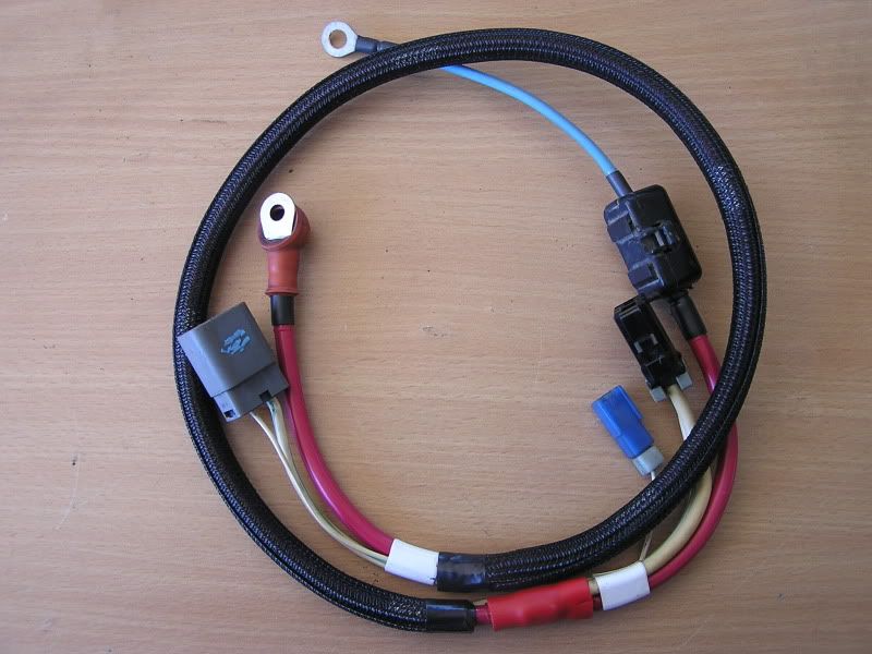
A "relay" is: a electric, HD, on/off switch. See, the SIZE of this, oem, twin relay?
Look closer. See the GAUGE, of the wires, attached to the relay?
Most relays require 4 wires, each. To activate the relay, (its coil)
two, light gauge wires...1. ignition power (maybe) 2. a ground, supplied
by the ECU (maybe) when it sees a ignition pulse-ground.
When activated, it, closes-together, the TWO, fatter gauge wires.
1. Generally the battery + source to:
2. the on-going +, fuel pump.
Do you NEED a relay? Yes & no.
It is a SAFETY measure. You stall your engine (for whatever reason)
you just lost the ignition-pulse, from your ignition, coil, (-) = kills the fuel pump.
In a Starquest, next-to, your air filter can, you'll see a black/white,
HEAVY gauge wire, to TEST, the fuel pump (send battery+ down the wire)
that, goes-around, the twin, oem, relay. (meaning it circumvents the relay)
Would you, install a toggle switch, in your TEST, wire?
Well, if you do, with a 15 amp switch, you'll note the switch will become HOT!
As in, it can't handle, TOO MANY, on-going, AMPS!
Btw, under your carpet, near the passangers feet, the black/white wire has,
a male/female union, as it GOES-AROUND, the twin relay.
Cough-cough, I suppose you are working-on, a Starquest.

Or is it on the kick-panel?
Btw, there are several "Ys" or "Ts", built into your harness', hidden.
Like this, black/white, further down the harness, has.
Btw...Black, w/red bands, indicates: a GROUND, wire! (not body ground)
A SWITCHED, ground!
Chapter 14 in the FSMs.
Just below the relay, splice-on, another, 14 gauge wire...take it
to the fuel pump. (black/white wire) CAKE!
You could: disconnect the connection, provide a wire, that goes to the
console, with a 35 AMP, toggle switch (igniton or battery, one side,
black/white, to the other side.
All you did was: SHORTEN, the black/white (by-passes the twin relay)
and gives YOU, the ability to "test" your fuel pump, power+, at the
flick-of-da-toggle.
But, you leave, all the relay wiring, STOCK!!
Some, race-rules, requires the relay, shut-down...cause you crashed,
maybe, knocked-out, can't turn-off your pump.
Yes, IF...you have the toggle-on, you just removed the safety feature,
of the twin relay.
Should you: increase the black/white wire gauge wire?
*I* would NOT! IF...I wanted, more copper wire to assist
the + source, pair-up, another wire, OF THE SAME GAUGE,
for its, entire lenght...or as close as you can = twin 14 gauge.
Single, 10 gauge wire is RETARDED, and never necessary, unless
you have twin, fuel pumps, or a stupid-large pump.
(you got a 10hp pump?
Always use, the KISS method! (keep it simple stupid)
Building from scratch? Use a single, 12 gauge wire, MAX!
(power-in, power-out, relay, only) & at least a 35amp toggle!
18 gauge is more than enough, for the relay...COIL, + & -
It...is NOT SAFE, to install a fuel pump relay, in a area,
where a COLLISION, could crush ANY relay!
(might not turn-off the pump!)
Think about that.
83 thru 87, twin, fuel pump relays are HUGE! (and bout $90, new)
I have been building fuel systems, from scratch, for over 30 years!
(big-ass pumps, sometimes) 14 gauge is enough!...12, just a CYA!
The BIGGER-da-gauge...ther more RESISTANCE, on that wire! THINK!
Is this Lexus's wire, 10 gauge? Ahhh, no.

Twin wires, are very nice, when you NEED them!
In-tank pumps are MUCH SMALLER (don't need to SUCK-UP fuel)
Hence, take-apart a Eclipse = wires smaller than a Starquest.
Yes, I C&Ped, what some GOOF, had suggested about converting-to,
in-tank pumps, into the SOS. Heeeee, don't know, shit-from-shineola!
I deleted it, several years later.
Boots...on-da-ground, baby!
Where does, the power come-from? Your ALTERNATOR!
The bigger your gauge-wire is (to the fuel pump) the HARDER,
the Alternator is working! THINK!
Meaning: BIGGER, ain't always, better!
Blower motors, are: AMP-HUNGRY! More-so, than a fuel pump!
Touch (with your fingers) the relays & heavy-gauge wires.
Are they hot? Or maybe just warm? Not enough to worry about
at high speed. THINK!
Invest, $30 for a lazer, meter. Works wonders!
Sometime, in 88 or 89, they were REDUCED, in there sizes.
(the oem fuel pump relay)
Ya see...most of the Starquest, electrical (not all) were, OVER-BUILT!
Short-comings were, the CHARGING, harness! (increased gauge wires
in 89s, only, but not enough for bigger Alts.)
Bigger Alternators, on the STOCK, charging harness?
you want to increase, the gauge wire of the fuel pump?
The solution:
Works wonders, on a STOCK, Alternator!
Most, HP, fuel pumps, pull about 9.5 amps...constantly!
Raise your hands...
increase, the gauge size, of black/white.
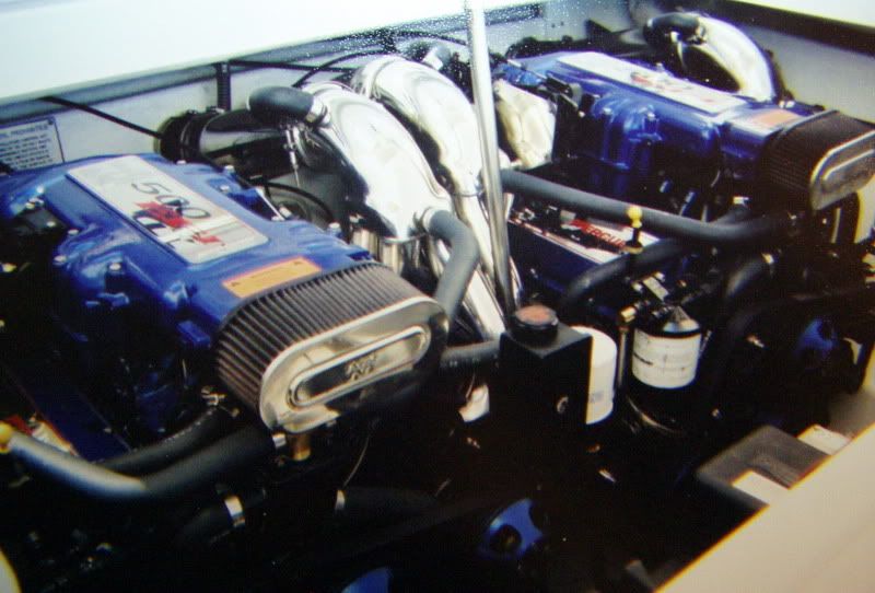
Good to know, you don't have twin, 500hp engines...cough, cough,
like our POWER BOATS HAVE!
The million dollar manual and AFFORDABLE parts too! USE IT!
http://starquest.i-x.net/viewforum.php?f=12
email: waynescoolworld@netzero.net USE IT!
http://starquest.i-x.net/viewforum.php?f=12
email: waynescoolworld@netzero.net USE IT!