I am working on a 60-1 trigger wheel that will mount between the front oil pump cover and the crank timing sprocket. To use this you will need to replace the balance shaft sprocket from the crank. Who wants balance shafts anyways? The trigger wheel will be pressed onto the MD128107 spacer from the mirage. Still need to figure out where to mount the magnetic pickup, but I think I can figure that out. The final result will be a trigger setup hidden and protected by the timing cover and a head with nothing on the back. This will work for those using aftermarket ECUs. The 60-2 wheel seems pretty universal from what I can tell.
This is intended for 2 guys locally that I am helping with the swap, but I might use it on my engine as well. Should help to clean up the back of the head. If we can work the bugs out, this may be offered for sale.
I'm going to make some measurements when I get home and post up a drawing.
"Hidden" 60-1 / 32-1 / etc. Trigger Wheels
Moderators: DJpowerHaus, mattmartindrift
-
DJpowerHaus
- Sir Post A Lot
- Posts: 1779
- Joined: Wed Apr 07, 2004 3:24 pm
- Location: Baltimore, MD
- Contact:
"Hidden" 60-1 / 32-1 / etc. Trigger Wheels
Last edited by DJpowerHaus on Fri Sep 19, 2008 10:09 am, edited 1 time in total.

Getting the engine bolted in is about 10% of the way there.
The next 80% can go quickly with help and skill.
That last 10% takes about as long as the 90% that came before it.
-
DJpowerHaus
- Sir Post A Lot
- Posts: 1779
- Joined: Wed Apr 07, 2004 3:24 pm
- Location: Baltimore, MD
- Contact:
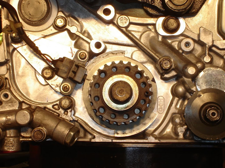
The balance shaft sprocket is 3.95" in diameter. The print out I made was a bit over 4" and was too big. Looks like a 3.5" trigger wheel would be best. Electromotive P/N: 230-72635. Most ECUs that I have researched specify that the mag sensor needs to be 11 teeth or about 60 degrees from top dead center. This puts the sensor right in the open space where the balance shaft used to be. NICE! (TDC on the on the trigger wheel is relative to the sensor so this isn't too important, but it would be nice if TDC on the crank key way was TDC on the trigger.)
Not sure if the bolt that held the balance shaft idler to the block is adequate to hold the mag sensor in place. One bolt? Maybe a pin can solve this. It seems to be in the perfect spot.
One problem I found was that the Mitsubishi spacer has some play at the keyway allowing it to move around a few degrees. I think this can be solved with a shim during install, or a pin holding it to the lower timing sprocket.
Getting the engine bolted in is about 10% of the way there.
The next 80% can go quickly with help and skill.
That last 10% takes about as long as the 90% that came before it.
-
DJpowerHaus
- Sir Post A Lot
- Posts: 1779
- Joined: Wed Apr 07, 2004 3:24 pm
- Location: Baltimore, MD
- Contact:
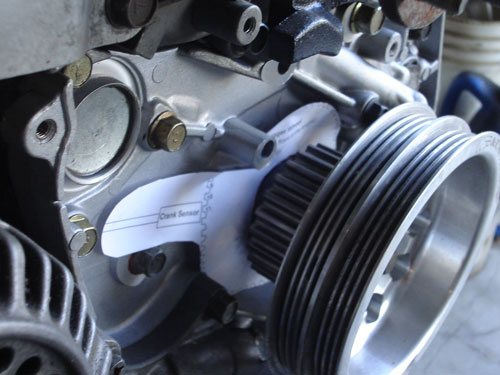
Here is where this will sit behind the timing sprocket.
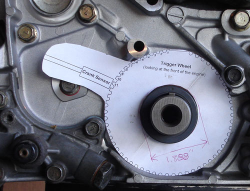
This is the trigger wheel picture I printed out. Its about 4" which is just a tad too large.
Getting the engine bolted in is about 10% of the way there.
The next 80% can go quickly with help and skill.
That last 10% takes about as long as the 90% that came before it.
-
jeffball610
- Too Much Time on His Hands
- Posts: 619
- Joined: Wed Feb 22, 2006 5:29 am
- Location: Las Vegas, NV
Sounds like a great idea. How will you adjust timing after the cover is installed? Most of us don't mess with the timing once it's set, but it would be nice to know you can adjust it. What will plug the rear hole from the old CAS? I think the 2G has a plug doesn't it? Or maybe 2 pieces like what covers the exhaust cam? I'm sure you already have that figured out. I'm interested to see what you come up with.
-
DJpowerHaus
- Sir Post A Lot
- Posts: 1779
- Joined: Wed Apr 07, 2004 3:24 pm
- Location: Baltimore, MD
- Contact:
95-96 cars have a round blockoff for the intake cam. I think the P/N is MD184946. I found one in a junkyard that I have in my spare motor. If anyone knows for sure, please let us know.
As far as adjustment, I'm going to see if I can slot the bracket for the mag sensor to move a few degrees. Also, most ECUs will let you adjust it in the software a tad.
Bill, if I gave you the part numbers, could you front me for a few months and put together a prototype while I'm away?
FYI. Having only a crank trigger means that there is no cam reference trigger and therefore you cannot do full sequential injection. Shouldn't really make a difference. Maybe one day we can design cam trigger.
Getting the engine bolted in is about 10% of the way there.
The next 80% can go quickly with help and skill.
That last 10% takes about as long as the 90% that came before it.
-
DJpowerHaus
- Sir Post A Lot
- Posts: 1779
- Joined: Wed Apr 07, 2004 3:24 pm
- Location: Baltimore, MD
- Contact:
I checked it out and it looks like it would be a 32-1 trigger. I imagine you set up some ECUs to use this. I'm very curious. I can set the Autronic up to do this, but I'll need a cam trigger to make it work.
I'll have to check with the guys that I'm helping to do the swap and see what ECU they pick and what trigger wheel types it supports.
I'll have to check with the guys that I'm helping to do the swap and see what ECU they pick and what trigger wheel types it supports.
Getting the engine bolted in is about 10% of the way there.
The next 80% can go quickly with help and skill.
That last 10% takes about as long as the 90% that came before it.
-
DJpowerHaus
- Sir Post A Lot
- Posts: 1779
- Joined: Wed Apr 07, 2004 3:24 pm
- Location: Baltimore, MD
- Contact:
Will and Craig seem pretty set on the MegaSquirt II. I've started reading up on it and it seems that a 32-1 would work. Not sure if the tooth profile would work, but its worth experimenting.
Where can I buy a mag sensor and how can I bench test my setup?
Where can I buy a mag sensor and how can I bench test my setup?
Getting the engine bolted in is about 10% of the way there.
The next 80% can go quickly with help and skill.
That last 10% takes about as long as the 90% that came before it.
DJ, a 32-1 will work with msII, as far as the cheapest sensor, i just used what i had laying around, which happened to be off a late 90's escort 1.9L. It's angled weird, which i didn't like, but until I get to that stage, it works for mock up and bench testing. The biggest drawback to using the stock crank pulley for the balance shaft belt is the "lip" on the back of it, it confused the vr sensor, I just ground it down between the teeth when i ground out one tooth. I didn't thing far enough ahead to grind out whatever tooth should have been, i ground out one straight up with the crank at tdc. When bench testing, i just hooked the vr sensor to an instlled msII on the g54b car, taped the gear to a socket, stuck that in a cordless drill and spun the gear. Now i just gotta figure out a good mount for the vr sensor. I'm using your idea of the old balance shaft belt tensioner pulley bolt hole with an alignment dowel stuck into the pump somewhere, just haven't got it all done yet.
-
DJpowerHaus
- Sir Post A Lot
- Posts: 1779
- Joined: Wed Apr 07, 2004 3:24 pm
- Location: Baltimore, MD
- Contact:
So, when using the 32 tooth Balance shaft, do I grind out the tooth at TDC? I think I can turn down that lip to get rid of it.
This is one thing among many I'm trying to sort out while I'm up here at Bill's
This is one thing among many I'm trying to sort out while I'm up here at Bill's
Last edited by DJpowerHaus on Tue Jul 19, 2011 9:38 am, edited 1 time in total.
Getting the engine bolted in is about 10% of the way there.
The next 80% can go quickly with help and skill.
That last 10% takes about as long as the 90% that came before it.
-
DJpowerHaus
- Sir Post A Lot
- Posts: 1779
- Joined: Wed Apr 07, 2004 3:24 pm
- Location: Baltimore, MD
- Contact:
Had Bill take the lip off of 2 of the balance pulleys today. Made a big discovery a few min later when I was looking to line up a sensor. Here's the big discovery:
SOHC - 38 teeth
DOHC - 32 teeth
Weird huh? Can I use the 38 teeth for anything? I'll get this figured out.
SOHC - 38 teeth
DOHC - 32 teeth
Weird huh? Can I use the 38 teeth for anything? I'll get this figured out.
Getting the engine bolted in is about 10% of the way there.
The next 80% can go quickly with help and skill.
That last 10% takes about as long as the 90% that came before it.
-
DJpowerHaus
- Sir Post A Lot
- Posts: 1779
- Joined: Wed Apr 07, 2004 3:24 pm
- Location: Baltimore, MD
- Contact:
I started making a bracket to hold a sensor, but put that to the side to ponder the possibility of moving the CAS to the front of the head. We have Bill's pile of stuff from his belt driven setup. We'll explore that for the time being before finishing up the other solution.
Getting the engine bolted in is about 10% of the way there.
The next 80% can go quickly with help and skill.
That last 10% takes about as long as the 90% that came before it.
-
DJpowerHaus
- Sir Post A Lot
- Posts: 1779
- Joined: Wed Apr 07, 2004 3:24 pm
- Location: Baltimore, MD
- Contact:
Someone posted this on another thread. Pretty neat design:
http://www.kigglyracing.com/parts/cranktrigger.htm
http://www.kigglyracing.com/parts/cranktrigger.htm
Getting the engine bolted in is about 10% of the way there.
The next 80% can go quickly with help and skill.
That last 10% takes about as long as the 90% that came before it.
I realize this is old but I thought other people may be interested also in what I found. It's a premade crank trigger kit.
http://www.distributorless.com/products ... -73002.php
http://www.distributorless.com/products ... -73002.php
Here is another option. I haven't tested these and am looking for confirmaion.
-----------------------------------------------------------------
FOR THE CRANK ANGLE SENSOR
-----------------------------------------------------------------
Hyundai front cover on 6-bolt for 2g Crank Angle Sensor
http://www.dsmtuners.com/forums/bolt-te ... ensor.html
-----------------------------------------------------------------
FOR THE CAM ANGLE SENSOR:
from http://www.roadraceengineering.com/1g2g ... echtip.htm
-----------------------------------------------------------------
The 97-up style cam angle sensor will bolt to the 1G head without any modification. The wire connector is different so you will need to make a connector for it or get one from a wrecking yard to plug in the wires. The main difference in the sensor is that it gives an opposite pulse from what the 95-96 sensor does. There are two ways to deal with it. (This also applies to swapping a 95-96 ECU with a 97-up ECU)
1) At the ignition coil, connect plug wires from cylinders 1 and 4 into the coil for 2 and 3. Connect the plug wires from cylinders 2 and 3 into the coil for 1 and 4.
or 2) At the smaller coil wire electrical connector, swap the trigger wires for the two coils. Cut the blue/red wire and the blue/black wire. Swap them and reconnect them.
If buying the 97 cam angle sensor parts new from the dealer you will need the following:
The Sensor and the bolt that holds it on.
1) MD327107 Sensor, Camshaft Position
1) MF140003 Bolt, 6mmx 12mm
The cast aluminum housing assembly that holds the sensor.
1) MD344722 Support, Camshaft Position Sensor
1) MD329502 Cover, Camshaft Position Sensor
1) MD329503 Gasket, Camshaft Position Sensor
3) MF140204 Bolt, Cover 6mm x 14mm
2) MF140025 Bolt, Support 8mm x 20mm
The piece that bolts to the end of the camshaft and the bolt itself.
1) MD327621 Cylinder, Camshaft Position Sensor
1) MF241261 Bolt, Camshaft
Expect to pay between $100 and $150 for the parts depending on the dealer.
-----------------------------------------------------------------
FOR THE CRANK ANGLE SENSOR
-----------------------------------------------------------------
Hyundai front cover on 6-bolt for 2g Crank Angle Sensor
http://www.dsmtuners.com/forums/bolt-te ... ensor.html
-----------------------------------------------------------------
FOR THE CAM ANGLE SENSOR:
from http://www.roadraceengineering.com/1g2g ... echtip.htm
-----------------------------------------------------------------
The 97-up style cam angle sensor will bolt to the 1G head without any modification. The wire connector is different so you will need to make a connector for it or get one from a wrecking yard to plug in the wires. The main difference in the sensor is that it gives an opposite pulse from what the 95-96 sensor does. There are two ways to deal with it. (This also applies to swapping a 95-96 ECU with a 97-up ECU)
1) At the ignition coil, connect plug wires from cylinders 1 and 4 into the coil for 2 and 3. Connect the plug wires from cylinders 2 and 3 into the coil for 1 and 4.
or 2) At the smaller coil wire electrical connector, swap the trigger wires for the two coils. Cut the blue/red wire and the blue/black wire. Swap them and reconnect them.
If buying the 97 cam angle sensor parts new from the dealer you will need the following:
The Sensor and the bolt that holds it on.
1) MD327107 Sensor, Camshaft Position
1) MF140003 Bolt, 6mmx 12mm
The cast aluminum housing assembly that holds the sensor.
1) MD344722 Support, Camshaft Position Sensor
1) MD329502 Cover, Camshaft Position Sensor
1) MD329503 Gasket, Camshaft Position Sensor
3) MF140204 Bolt, Cover 6mm x 14mm
2) MF140025 Bolt, Support 8mm x 20mm
The piece that bolts to the end of the camshaft and the bolt itself.
1) MD327621 Cylinder, Camshaft Position Sensor
1) MF241261 Bolt, Camshaft
Expect to pay between $100 and $150 for the parts depending on the dealer.
-
DJpowerHaus
- Sir Post A Lot
- Posts: 1779
- Joined: Wed Apr 07, 2004 3:24 pm
- Location: Baltimore, MD
- Contact:
Sorry I didnt follow up way back then. I did craig's swap with the 95-96 cam / crank trigger setup. The head was a large port head but it also had provisions for the cam sensor. Here is what we did for the crank sensor:
I had to use a little geometry to trim a 1G timing plate to be my new trigger plate. I'll be making one of these for my car in a few weeks. I'll try to have better documentation this time around.
I had to use a little geometry to trim a 1G timing plate to be my new trigger plate. I'll be making one of these for my car in a few weeks. I'll try to have better documentation this time around.
Getting the engine bolted in is about 10% of the way there.
The next 80% can go quickly with help and skill.
That last 10% takes about as long as the 90% that came before it.
-
DJpowerHaus
- Sir Post A Lot
- Posts: 1779
- Joined: Wed Apr 07, 2004 3:24 pm
- Location: Baltimore, MD
- Contact:
DJ, I can't seem to find any pics either. Your solution would work better than having to source specific parts.
Could you make up a bunch of extras or have Bill make them? There is a solution similar to yours but it runs ~$200 and I would rather support someone on here. I'm sure other people would like to buy one from you.
Could you make up a bunch of extras or have Bill make them? There is a solution similar to yours but it runs ~$200 and I would rather support someone on here. I'm sure other people would like to buy one from you.
I wasn't paying enough attention last time on this thread.
What I will be doing is taking the plate that DJ modified and cutting slots in it to make the trigger wheel for my Megasquirt install. Then putting the pickup like his. All it takes is a file and some aluminum bar. When I did the install on my Fiat I took the cranshaft pulley and slotted the back edge. Worked great with EDIS.
What I will be doing is taking the plate that DJ modified and cutting slots in it to make the trigger wheel for my Megasquirt install. Then putting the pickup like his. All it takes is a file and some aluminum bar. When I did the install on my Fiat I took the cranshaft pulley and slotted the back edge. Worked great with EDIS.
I haven't verified this yet but this is what I have found and intend on trying.
* The 95 Hyundai Elantra/Sonata Oil Pump is compatible with the 1990 Mitsubishi Eclipse.
* The 95 Sonata used a crank mounted sensor.
* The 90 Eclipse is a 6-bolt
* So the 95 Sonata oil pump must be a 6-bolt with a crank mounted sensor
Hyundai licensed the 4g63 from Mitsubishi and kept the 6-bolt but had to have the crank mounted sensor to meet OBD requirements.
Look up the 95 Sonata oil pump on ebay if you want to check yourself.
Ideally I would love to have someone get this physically in hand to confirm or deny it.
AustinTSI,
You are definitely on the right track! I have been researching this also to alleviate the cam sensor for use with RWD.
When you start talking Hyundai's, you enter the twilight zone of Mitsubishi technology....kind of like the weird part of Youtube.
Anyway, I believe it is a possibility. Check out these threads:
http://www.dsmtuners.com/forums/newbie- ... t151852269
http://www.dsmtuners.com/forums/bolt-te ... ensor.html
And if all else fails! https://www.extremepsi.com/store/produc ... ctid=23253
I had found those articles previously but they all keep mentioning that the oil pan is curved and several other issues. The curved pan means that it would be technically a 2G but has 1G parts. But if you look at the 95 model as I mentioned above it says that it is compatible with a 91 which has a flat oil pan.
I have been trying to find a service manual for a 95 sonata but I think the best thing to do would be to find one at a junk yard and just take one apart and confirm everything visually.
I have been trying to find a service manual for a 95 sonata but I think the best thing to do would be to find one at a junk yard and just take one apart and confirm everything visually.