Greetings all - i am in the middle of putting a 4g63T into a sandrail -
Ive got the entire engine harness,ECU and MPI. Ive got 3 basic questions. (well basic to you all, not so basic to me)
1) what pins need to be energized constanntly
2)what pins needs to be energized only while cranking
3)what pins need to be energized while in the run position.
I am doing my own ignition (prob push button style)
Thanks for any help -
-dave
Sandrail wiring
Moderators: DJpowerHaus, mattmartindrift
Thank you very much sir - Take a look at these pic's if you would.
Pin 103 is my main prob i think. I know i can just splice into it @ the ECU but i would rather get it from the plug if i can.
I think this is what is refered to as the C-58 plug on
http://www.projectzerog.com/wiring-how_to.shtml

What is confusing me is i have a different number of pins then the one on the FAQ(i got 2 more). I wish the pinout also listed the wire color so i could verify its really the same plug.

This is what i think is C-67 and suposed to contain +12V Constant (10A fuse) for backup power to the ECU (pin 103) but it looks nothing like the plug on the FAQ but it is near the 3 yellow ECU plugs on the engine harness.

Finnaly i have 2 other connectors that are single pins one with a rather LARGE wire that i dont know what they are.
This harness was from a 92-93 AWD / MT car
Pin 103 is my main prob i think. I know i can just splice into it @ the ECU but i would rather get it from the plug if i can.
I think this is what is refered to as the C-58 plug on
http://www.projectzerog.com/wiring-how_to.shtml
What is confusing me is i have a different number of pins then the one on the FAQ(i got 2 more). I wish the pinout also listed the wire color so i could verify its really the same plug.
This is what i think is C-67 and suposed to contain +12V Constant (10A fuse) for backup power to the ECU (pin 103) but it looks nothing like the plug on the FAQ but it is near the 3 yellow ECU plugs on the engine harness.
Finnaly i have 2 other connectors that are single pins one with a rather LARGE wire that i dont know what they are.
This harness was from a 92-93 AWD / MT car
-
89coltgt
- Too Much Time on His Hands
- Posts: 584
- Joined: Wed Apr 11, 2007 2:50 am
- Location: Ste Genevieve, MO
Here is how I wired mine:
+12v constant wires:
20A fuse to pin# 10 on mpi relay
10A fuseto pin# 103 on ecu
Starter signal *I used the solenoid wire to energize a seperate relay to isolate the ecu.
Pin# 108 on ecu
Grounded wires
Pin# 6 on mpi relay
Pin# 104, 106, and 101 on ecu
+12v energized during start/run
Pin# 110 on ecu
Pin# 3 on mpi relay
I also used pin#2 on mpi relay to energize a 30A relay to power the fuel pump.
-
89coltgt
- Too Much Time on His Hands
- Posts: 584
- Joined: Wed Apr 11, 2007 2:50 am
- Location: Ste Genevieve, MO
No, I have a 4g63t swapped d50 pickup. The truck was carburated, so I had to treat the harness as a complete seperate sytem like you will have to do.Dave99gst wrote:When you says yours.. do you got a sandrail ? if so i would really like to see pics.89coltgt wrote:Here is how I wired mine:
Thank you for all the info I am really close to putting the harness on the motor.
-
Professor Quest
- Addict
- Posts: 136
- Joined: Sun Nov 30, 2008 8:25 pm
- Location: High Desert, Albuquerque, NM. The NUCLEAR state!
It really helps if you have a diagram of the system you have. (year, model, type)
What I do know is Mitsu related:
Switched ignition ONE: Black/white (usually ignition & fuel pump)
Switched ignition TWO Blue/red (this prevents overloading ignition one)
Switched Acc. Blue/white (radio-wiper-blower motor-power windows etc)
Battery power ID as (B+) or (+)...sent to the ignition switch via a large White/black and frequenty passes thru a fusible link wire or a small plastic push-in type that is also a SLOW BURN fuse link.
Example: If the ign. 2 leaves the ignition switch as Blue/red (12 gauge) it may arrive at the ECU as RED (18 gauge) only. (often two of them)
Things that need a memory? An ETAC (if used) and the stereo. Full time B+ but thru the fuse panel.
A heated O2? Better to pull power from ignition TWO...so ignition ONE gets FULL POWER to the coil & fuel pump etc.
MANY ignition switch connectors have a 6 pin connector. However, look inside the connector....it MAY be a 6 pin connector, but only have 5 terminals inside it.
Early starquest was NOT OVERLOADED with excessive power demands so a 83 did'nt have ignition TWO. Hence, only 5 terminals inside the 6 pin connector. Sooooo, you pull from "ACC"....not ignition one.
*IF* you decide your gonna need a RELAY, DO NOT USE THOSE CHEAP-ASS RELAYS they sell at places where they sell foglights etc.
Pull the NICE, HD RELAYS from a boneyard and CUT....a portion of the harness to make it a HD, plug & play relay.
Where are they? Your electric fans (round in a starquest) and so is the foglights.
Biggest relays to smaller
1. Starter solinoid (fixed)
2. fuel pump relay (susupended)
3. cooling fans/foglights (suspended)
4. blowermotor (suspended)
COPPER! priced like GOLD! "get-da-good-stuff"

There are two types of test lights out there. The COMMON one, alligator and a pointer-end SPELLS DISASTER to a computer. NEVER USE THOSE!
The OTHER type has TWO alligators for BOTH positive & negative to power you COMPUTER type of a test light.
1. A red diode will come to tell you you light is powerd.
2. when you probe a positive ANOTHER red diode indicates you probed a positive.
3. A GREEN diode will light to indicate you just probed a NEGATIVE.....
WITHOUT FREAKING-OUT your ECU.
What you DO NOT want to do is DRAW POWER from ignition one OTHER than your ignition system.
Black/yellow is DIRECT (from your ignition switch) to your STARTER SOLINOID (a huge fricking relay) and any other relay is ALARM RELATED to STOP currant to REACH the starter if the alarm goes off. In other words....you would not need it/install one IF the car did not come from the factory with a alarm system.
The ECU harness in a starquest: ALSO has the SENDERS WIRES within it.
That would be:
the oil pressure sender wire
the temperture gauge wire (in your dash)..... (usually a seperate, smaller connector that heads over to the dash) yellow/blue & yellow green?
and COULD be wired for EGR position info too in a Eclipse etc. (useless )
)
What I do know is Mitsu related:
Switched ignition ONE: Black/white (usually ignition & fuel pump)
Switched ignition TWO Blue/red (this prevents overloading ignition one)
Switched Acc. Blue/white (radio-wiper-blower motor-power windows etc)
Battery power ID as (B+) or (+)...sent to the ignition switch via a large White/black and frequenty passes thru a fusible link wire or a small plastic push-in type that is also a SLOW BURN fuse link.
Example: If the ign. 2 leaves the ignition switch as Blue/red (12 gauge) it may arrive at the ECU as RED (18 gauge) only. (often two of them)
Things that need a memory? An ETAC (if used) and the stereo. Full time B+ but thru the fuse panel.
A heated O2? Better to pull power from ignition TWO...so ignition ONE gets FULL POWER to the coil & fuel pump etc.
MANY ignition switch connectors have a 6 pin connector. However, look inside the connector....it MAY be a 6 pin connector, but only have 5 terminals inside it.
Early starquest was NOT OVERLOADED with excessive power demands so a 83 did'nt have ignition TWO. Hence, only 5 terminals inside the 6 pin connector. Sooooo, you pull from "ACC"....not ignition one.
*IF* you decide your gonna need a RELAY, DO NOT USE THOSE CHEAP-ASS RELAYS they sell at places where they sell foglights etc.
Pull the NICE, HD RELAYS from a boneyard and CUT....a portion of the harness to make it a HD, plug & play relay.
Where are they? Your electric fans (round in a starquest) and so is the foglights.
Biggest relays to smaller
1. Starter solinoid (fixed)
2. fuel pump relay (susupended)
3. cooling fans/foglights (suspended)
4. blowermotor (suspended)
COPPER! priced like GOLD!
There are two types of test lights out there. The COMMON one, alligator and a pointer-end SPELLS DISASTER to a computer. NEVER USE THOSE!
The OTHER type has TWO alligators for BOTH positive & negative to power you COMPUTER type of a test light.
1. A red diode will come to tell you you light is powerd.
2. when you probe a positive ANOTHER red diode indicates you probed a positive.
3. A GREEN diode will light to indicate you just probed a NEGATIVE.....
WITHOUT FREAKING-OUT your ECU.
What you DO NOT want to do is DRAW POWER from ignition one OTHER than your ignition system.
Black/yellow is DIRECT (from your ignition switch) to your STARTER SOLINOID (a huge fricking relay) and any other relay is ALARM RELATED to STOP currant to REACH the starter if the alarm goes off. In other words....you would not need it/install one IF the car did not come from the factory with a alarm system.
The ECU harness in a starquest: ALSO has the SENDERS WIRES within it.
That would be:
the oil pressure sender wire
the temperture gauge wire (in your dash).....
and COULD be wired for EGR position info too in a Eclipse etc. (useless
The million dollar manual and AFFORDABLE parts too! USE IT!
http://starquest.i-x.net/viewforum.php?f=12
email: waynescoolworld@netzero.net USE IT!
http://starquest.i-x.net/viewforum.php?f=12
email: waynescoolworld@netzero.net USE IT!
-
89coltgt
- Too Much Time on His Hands
- Posts: 584
- Joined: Wed Apr 11, 2007 2:50 am
- Location: Ste Genevieve, MO
^I think you are straying away from what the op is actually doing. He simply needs to know what wires on the harness ne constant 12v/switch 12v, starter signals, grounds, etc. There are only a few wires that have to be tapped into, and all of this can be done through the plugs on the harness that plug into the chassis and there is the other one that runs out to the battery but that many plug in right at the chassis plugs as well.
Correct But , i truly do appreciate everyone taking the time to chime in with there thoughts/opinions.!89coltgt wrote: He simply needs to know what wires on the harness ne constant 12v/switch 12v, starter signals, grounds, etc.
I started a project thread for ya all :
http://projectzerog.com/forum/viewtopic ... 1166#11166
-
Professor Quest
- Addict
- Posts: 136
- Joined: Sun Nov 30, 2008 8:25 pm
- Location: High Desert, Albuquerque, NM. The NUCLEAR state!
There's a lil' more INFO that you'll appreciate knowing too.
Facts:
1. any wire (positive, negative or SENSOR wiring) becomes an ARIEL...an ANTENNA.
Because the SENSOR wiring is nearly ALWAYS protected by a "SHIELDED-GROUND" to prevent the TRANSFER of HIGHER VOLTAGE to enter the SENSOR wiring...causing the engines ECU to freakout, you need to use the entire OEM harness, or use GROUND SHIELDED WIRES (and ground one end)
so the SIGNAL arrives at the ECU WITHOUT UNWANTED VOLTAGE JUMPING INTO THAT WIRE.
http://starquest.i-x.net/viewtopic.php? ... d5f52994eb
2. How IMPORTANT this is....this is WHY the O2 wire IS SEPERATED FROM THE MAIN HARNESS....and the LENGHT it is, *WILL* alter the POWER of that signal.
A COLD O2 makes zero volts....but as it warms-up moves to .9 volts.
Example: You would NEVER want your HEADLIGHT wiring INSIDE the same harness because once you turn on your lights...that HIGHER VOLTAGE is gonna want to JUMP INSIDE the O2 signal wiring...messing with the ECU.
A factory antenna wire IS....ground-shielded too, same as your CABLE TV.
Most would call it: "INTERFERANCE" to your radio, your TV......or your ECU!
*IF*...you were to remove the entire ECU harness you'll note a handful of GROUNDED SHIELED SCREWS that would would need to remove.
In a Starquest....that would be BLACK....with RED BANDS around those wires.
That is WHERE the SURROUNDED shielded-ground comes from...the body.
OTHER ground shielded sensor wires are:
the detonation sensor
the impulse from the Distributor (if used)
cam position (if used)
CTS...on many cars
Note: one shielded ground screw could "T"-off to supply grounds to several sensor wires.
Yes...you can build it from SCRATCH, if you understand the basics.
The million dollar manual and AFFORDABLE parts too! USE IT!
http://starquest.i-x.net/viewforum.php?f=12
email: waynescoolworld@netzero.net USE IT!
http://starquest.i-x.net/viewforum.php?f=12
email: waynescoolworld@netzero.net USE IT!
-
Professor Quest
- Addict
- Posts: 136
- Joined: Sun Nov 30, 2008 8:25 pm
- Location: High Desert, Albuquerque, NM. The NUCLEAR state!
Using BUTT-CONNECTORS is a NO-NO!  SOLDER....SOLDER & HEAT SHRINK IT!
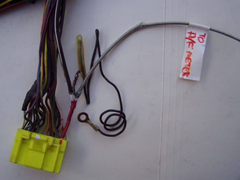
Here....tapping into the O2 signal AT the ECU harness connector with a shielded ground wire prevents UNWANTED VOLTAGE jumping into this wire cause the gauge signal wire MIGHT pass by higher voltage wires.
18 gauge...braided signal wire & gronded shield LOOP.
However...I think that having a SEPERATE WIDEBAND O2 that sends the signal to AF gauge is a better way to go. That way there's NO-WAY that ECU could be INTERFERED with.
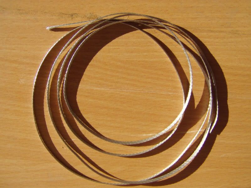
Here....braided grounded shield LOOP that you can slide-in whatever 18 gauge COLOR you may prefer to ID each wire.
At one end, you're just gonna install an RING EYELET to ground the surrounding shield.
Myself.... I'd go GUT the entire harness from a car that nobody ever jacked with it.
Then, I'd install one of my lil' gadets to OVER-RULE the AFR so I can richen the A/F ratio by simply turning a knob in the dash.
Btw....thanks for the pics of your rail job. Very nice!
As you leave the battery...make sure you GROUND THE FRAME FIRST....then onto the engine block.
And...a common misunderstanding: Just because the metal-ta-metal, engine to trans is thought to be OK.... NOT! Another short, ground cable is used to ASSURE both are grounded WELL!
More here:
http://starquest.i-x.net/viewtopic.php? ... b3403d2628
And I hope you have the REAR STEERING BRAKES to control that MONSTER! Cause I think your right....the front tires are likely to be OFF-DA-GROUND!
Here....tapping into the O2 signal AT the ECU harness connector with a shielded ground wire prevents UNWANTED VOLTAGE jumping into this wire cause the gauge signal wire MIGHT pass by higher voltage wires.
18 gauge...braided signal wire & gronded shield LOOP.
However...I think that having a SEPERATE WIDEBAND O2 that sends the signal to AF gauge is a better way to go. That way there's NO-WAY that ECU could be INTERFERED with.
Here....braided grounded shield LOOP that you can slide-in whatever 18 gauge COLOR you may prefer to ID each wire.
At one end, you're just gonna install an RING EYELET to ground the surrounding shield.
Myself....
Then, I'd install one of my lil' gadets to OVER-RULE the AFR so I can richen the A/F ratio by simply turning a knob in the dash.
Btw....thanks for the pics of your rail job. Very nice!
As you leave the battery...make sure you GROUND THE FRAME FIRST....then onto the engine block.
And...a common misunderstanding: Just because the metal-ta-metal, engine to trans is thought to be OK....
More here:
http://starquest.i-x.net/viewtopic.php? ... b3403d2628
And I hope you have the REAR STEERING BRAKES to control that MONSTER!
The million dollar manual and AFFORDABLE parts too! USE IT!
http://starquest.i-x.net/viewforum.php?f=12
email: waynescoolworld@netzero.net USE IT!
http://starquest.i-x.net/viewforum.php?f=12
email: waynescoolworld@netzero.net USE IT!
-
DJpowerHaus
- Sir Post A Lot
- Posts: 1779
- Joined: Wed Apr 07, 2004 3:24 pm
- Location: Baltimore, MD
- Contact:
You should be able to use an ohm meter to trace each wire from those chassis connectors to either an ECU pin or a plug on the harness. I usually only use my meter's audible mode to answer this for me. If its making noise, Im connected to the other end of the wire, or a wire that connects into the one I'm touching.
You should only need to have labeled the engine connectors and an ECU pinout that you can find on this site and others to identify every wire in the harness. There is no need for a pin out of every chassis connector.
Label as you go.
You should only need to have labeled the engine connectors and an ECU pinout that you can find on this site and others to identify every wire in the harness. There is no need for a pin out of every chassis connector.
Label as you go.

Getting the engine bolted in is about 10% of the way there.
The next 80% can go quickly with help and skill.
That last 10% takes about as long as the 90% that came before it.
-
Professor Quest
- Addict
- Posts: 136
- Joined: Sun Nov 30, 2008 8:25 pm
- Location: High Desert, Albuquerque, NM. The NUCLEAR state!
Two failed ECU/FUEL PUMP relays? Odds are about a million to one of finding a SINGLE failure.
The OEM Starquest ones are so reliable....Mitsu DOWN-SIZED them as the years passed. I gather an Eclipse would have had a smaller one.
Those Starquest relays are 8 pins cause it had TWO relays in one box.
The OEM Starquest ones are so reliable....Mitsu DOWN-SIZED them as the years passed. I gather an Eclipse would have had a smaller one.
Those Starquest relays are 8 pins cause it had TWO relays in one box.
The million dollar manual and AFFORDABLE parts too! USE IT!
http://starquest.i-x.net/viewforum.php?f=12
email: waynescoolworld@netzero.net USE IT!
http://starquest.i-x.net/viewforum.php?f=12
email: waynescoolworld@netzero.net USE IT!